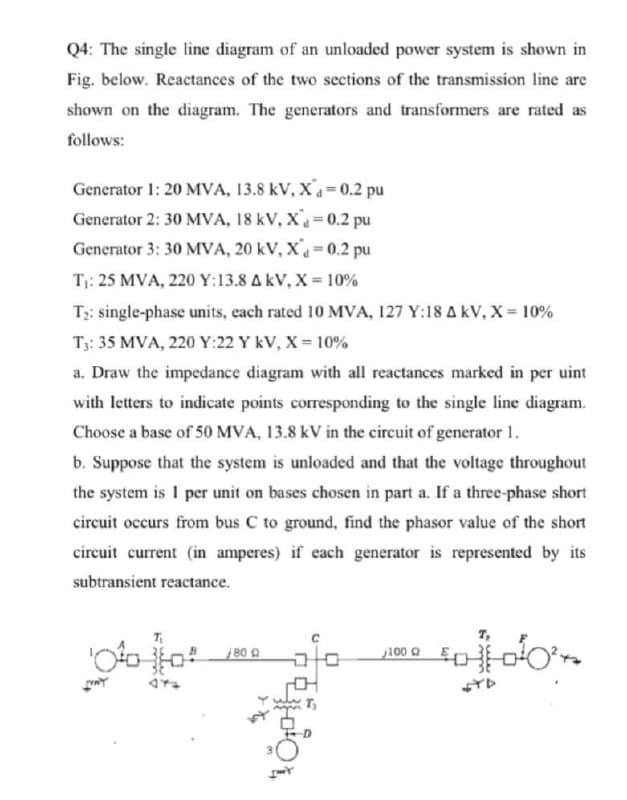
Q4: The single line diagram of an unloaded power system is shown in Fig. below. Reactances of the two sections of the transmission line are shown on the diagram. The generators and transformers are rated as follows: Generator 1: 20 MVA, 13.8 kV, X=0.2 pu Generator 2: 30 MVA, 18 kV, X = 0.2 pu Generator 3: 30 MVA, 20 kV, X«=0.2 pu Tị: 25 MVA, 220 Y:13.8 AkV, X = 10% T;: single-phase units, each rated 10 MVA, 127 Y:18 A kV, X = 10% T;: 35 MVA, 220 Y:22 Y kV, X= 10% a. Draw the impedance diagram with all reactances marked in per uint with letters to indicate points corresponding to the single line diagram. Choose a base of 50 MVA, 13.8 kV in the circuit of generator 1. b. Suppose that the system is unloaded and that the voltage throughout the system is I per unit on bases chosen in part a. If a three-phase short circuit occurs from bus C to ground, find the phasor value of the short circuit current (in amperes) if each generator is represented by its subtransient reactance. j 80 Q -머
Q4: The single line diagram of an unloaded power system is shown in Fig. below. Reactances of the two sections of the transmission line are shown on the diagram. The generators and transformers are rated as follows: Generator 1: 20 MVA, 13.8 kV, X=0.2 pu Generator 2: 30 MVA, 18 kV, X = 0.2 pu Generator 3: 30 MVA, 20 kV, X«=0.2 pu Tị: 25 MVA, 220 Y:13.8 AkV, X = 10% T;: single-phase units, each rated 10 MVA, 127 Y:18 A kV, X = 10% T;: 35 MVA, 220 Y:22 Y kV, X= 10% a. Draw the impedance diagram with all reactances marked in per uint with letters to indicate points corresponding to the single line diagram. Choose a base of 50 MVA, 13.8 kV in the circuit of generator 1. b. Suppose that the system is unloaded and that the voltage throughout the system is I per unit on bases chosen in part a. If a three-phase short circuit occurs from bus C to ground, find the phasor value of the short circuit current (in amperes) if each generator is represented by its subtransient reactance. j 80 Q -머

Power System Analysis and Design (MindTap Course List)
6th Edition
ISBN:9781305632134
Author:J. Duncan Glover, Thomas Overbye, Mulukutla S. Sarma
Publisher:J. Duncan Glover, Thomas Overbye, Mulukutla S. Sarma
Chapter3: Power Transformers
Section: Chapter Questions
Problem 3.49P: Consider the single-Line diagram of a power system shown in Figure 3.42 with equipment ratings...

Related questions

Concept explainers
Three-Phase Transformers
Three-segment transformers are a type of transformer used to transform voltages of electrical systems into three ranges. Two type transformers are shell-type transformer and core type transformer. In brief, it could be described because of the exquisite kinds of configurations.
Transformer
Ever since electricity has been created, people have started using it in its entirety. We see many types of Transformers in the neighborhoods. Some are smaller in size and some are very large. They are used according to their requirements. Many of us have seen the electrical transformer but they do not know what work they are engaged in.
Question
100%
Transcribed Image Text:Q4: The single line diagram of an unloaded power system is shown in
Fig. below. Reactances of the two sections of the transmission line are
shown on the diagram. The generators and transformers are rated as
follows:
Generator 1: 20 MVA, 13.8 kV, X=0.2 pu
Generator 2: 30 MVA, 18 kV, X 0.2 pu
Generator 3: 30 MVA, 20 kV, X=0.2 pu
T: 25 MVA, 220 Y:13.8 AkV, X = 10%
T2: single-phase units, cach rated 10 MVA, 127 Y:18 A kV, X = 10%
T3: 35 MVA, 220 Y:22 Y kV, X = 10%
a. Draw the impedance diagram with all reactances marked in per uint
with letters to indicate points corresponding to the single line diagram.
Choose a base of 50 MVA, 13.8 kV in the circuit of generator 1.
b. Suppose that the system is unloaded and that the voltage throughout
the system is I per unit on bases chosen in part a. If a three-phase short
circuit occurs from bus C to ground, find the phasor value of the short
circuit current (in amperes) if each generator is represented by its
subtransient reactance.
7,
j 80
j100
Expert Solution
This question has been solved!
Explore an expertly crafted, step-by-step solution for a thorough understanding of key concepts.

This is a popular solution!

Trending now
This is a popular solution!

Step by step
Solved in 2 steps with 3 images

Knowledge Booster


Learn more about
Need a deep-dive on the concept behind this application? Look no further. Learn more about this topic, electrical-engineering and related others by exploring similar questions and additional content below.Recommended textbooks for you
Power System Analysis and Design (MindTap Course …
Electrical Engineering
ISBN:
9781305632134
Author:
J. Duncan Glover, Thomas Overbye, Mulukutla S. Sarma
Publisher:
Cengage Learning
Power System Analysis and Design (MindTap Course …
Electrical Engineering
ISBN:
9781305632134
Author:
J. Duncan Glover, Thomas Overbye, Mulukutla S. Sarma
Publisher:
Cengage Learning