
Elements Of Electromagnetics
7th Edition
ISBN: 9780190698614
Author: Sadiku, Matthew N. O.
Publisher: Oxford University Press
expand_more
expand_more
format_list_bulleted
Related questions
Concept explainers
Question
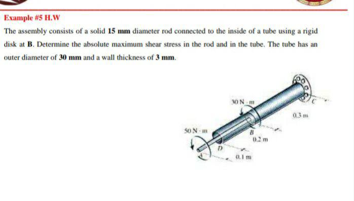

Transcribed Image Text:Example #5 H.W
The assembly consists of a solid 15 mm diameter rod connected to the inside of a tube using a rigid
disk at B. Determine the absolute maximum shear stress in the rod and in the tube. The tube has an
outer diameter of 30 mm and a wall thickness of 3 mm.
30N m
0,3 m
S0 N m
0.2 m
Expert Solution
This question has been solved!
Explore an expertly crafted, step-by-step solution for a thorough understanding of key concepts.

This is a popular solution

Trending nowThis is a popular solution!

Step by stepSolved in 2 steps with 2 images

Knowledge Booster


Learn more about
Need a deep-dive on the concept behind this application? Look no further. Learn more about this topic, mechanical-engineering and related others by exploring similar questions and additional content below.Similar questions
- 5. The drive shaft AB of an automobile is to be designed as a thin-walled tube. The engine delivers 180 hp when the shaft is turning at 900 rev/min. Determine the minimum thickness of the shaft's wall if the shaft's outer diameter is 3.2 in. The material has an allowable shear stress of T allow = 9 ksi. D T —— ▬▬▬▬▬ -arrow_forwardThe shaft has a diameter d and is subjected to the loadings shown. Determine the principal stresses and the maximum in-plane shear stress at point A. The bearings only support vertical reactions.arrow_forwardThe yoke-and-rod connection is subjected to a 40 mm 5 kN, tensile force of 5 kN. Determine the average normal stress in each rod and the average shear stress in the pin A between the members. 30 mm 25 mm 5 kNarrow_forward
- C-S at E: 40 mm TB The pipe assembly is subjected to the loads shown. Determine the state of 1 kN 30 mm stress at point A on cross-section E and show the results on a volume element. (Ans: 0A = -5.615 MPa, Ta = 5.372 MPa) 0.4 m X 0.3 m B 0.5 m 0.1 m 0.1 m 60" E 0.25 m 2 kNarrow_forwardDetermine the shear stress at point B on the web of the cantilevered strut at section a–a.arrow_forwardDetermine the principal stress and absolute maximum shear stress developed at point B on the cross section of the bracket at section a-a. Show the Mohr's circle for point B. -300 mm 150 mm 2.5 kN a 12 mm B 6 mm www 6 mm 5 4 A, 36 mm'36 mm Section a - a 6 mmarrow_forward
- The copper pipe has an outer diameter of 3 in. and an inner diameter of 2.5 in. If it is tightly secured to the wall at C and a uniformly distributed torque is applied to it as shown, determine the shear stress at points A and B. These points lie on the pipe’s outer surface. Sketch the shear stress on volumeelements located at A and B.arrow_forwardThe tension member is fastened together using two bolts, one on each side of the member as shown. Each bolt has a diameter of 0.3 inin. The allowable shear stress for the bolts is τallow=14 ksiτallow=14 ksi and the allowable average normal stress is σallow=20 ksσallow=20 ksi. Determine the maximum load PP that can be applied to the member.arrow_forwardThe solid circular shaft is subjected to an internal torque of T = 5 kN # m. Determine the shear stress at points A and B. Represent each state of stress on a volume element.arrow_forward
- The following shaft consists of a tube AB and a solid rod BC. The tube has an inner diameter of 25 mm and an outer diameter of 30 mm. The rod has a diameter of 15 mm. Determine the average normal stress at point D. The average normal stress at point D isarrow_forwardThe shaft is used to transmit 30 hp while turning at 600 rpm. Determine the maximum shear stress in the shaft. The segments are connected together using a fillet weld having a radius of 0.18 in.arrow_forwardQuestion: Determine the average shear stress in the single pin A and double pin B as well as the average normal stress in member AD if member BA is subjected to load of 500N/m. Pin A and pin B have diameters of 20mm and 10mm respectively while member AD has a square cross section of 30 mm on each side. D 3000 mm 500 N/m B A 2000 mm 2000 mmarrow_forward
arrow_back_ios
SEE MORE QUESTIONS
arrow_forward_ios
Recommended textbooks for you
- Elements Of ElectromagneticsMechanical EngineeringISBN:9780190698614Author:Sadiku, Matthew N. O.Publisher:Oxford University Press
 Mechanics of Materials (10th Edition)Mechanical EngineeringISBN:9780134319650Author:Russell C. HibbelerPublisher:PEARSON
 Thermodynamics: An Engineering ApproachMechanical EngineeringISBN:9781259822674Author:Yunus A. Cengel Dr., Michael A. BolesPublisher:McGraw-Hill Education
  Control Systems EngineeringMechanical EngineeringISBN:9781118170519Author:Norman S. NisePublisher:WILEY
 Mechanics of Materials (MindTap Course List)Mechanical EngineeringISBN:9781337093347Author:Barry J. Goodno, James M. GerePublisher:Cengage Learning
 Engineering Mechanics: StaticsMechanical EngineeringISBN:9781118807330Author:James L. Meriam, L. G. Kraige, J. N. BoltonPublisher:WILEY
Elements Of Electromagnetics
Mechanical Engineering
ISBN:9780190698614
Author:Sadiku, Matthew N. O.
Publisher:Oxford University Press
Mechanics of Materials (10th Edition)
Mechanical Engineering
ISBN:9780134319650
Author:Russell C. Hibbeler
Publisher:PEARSON
Thermodynamics: An Engineering Approach
Mechanical Engineering
ISBN:9781259822674
Author:Yunus A. Cengel Dr., Michael A. Boles
Publisher:McGraw-Hill Education
Control Systems Engineering
Mechanical Engineering
ISBN:9781118170519
Author:Norman S. Nise
Publisher:WILEY
Mechanics of Materials (MindTap Course List)
Mechanical Engineering
ISBN:9781337093347
Author:Barry J. Goodno, James M. Gere
Publisher:Cengage Learning
Engineering Mechanics: Statics
Mechanical Engineering
ISBN:9781118807330
Author:James L. Meriam, L. G. Kraige, J. N. Bolton
Publisher:WILEY