
Concept explainers
Videos
The diode in the circuit shown in Figure P1.53 is biased with a constant current source I. A sinusoidal signal
(b) If
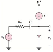
Figure P1.53
Want to see the full answer?
Check out a sample textbook solution
Chapter 1 Solutions
MICROELECT. CIRCUIT ANALYSIS&DESIGN (LL)


- The temperature dependence of resistance is also quantified by the relation R2=R1[ 1+(T2T1) ] where R1 and R2 are the resistances at temperatures T1 and T2, respectively, and is known as the temperature coefficient of resistance. If a copper wire has a resistance of 55 at 20C, find the maximum permissible operating temperature of the wire if its resistance is to increase by at most 20. Take the temperature coefficient at 20C to be =0.00382.arrow_forwardHow is a solid-state diode tested? Explain.arrow_forwardE.) The voltage on Figure Q1 is connected across a 0.15 2 resistive load. Calculate the power dissipated in this resistor. F.) Sketch the circuit for an ac supply input to a full-wave diode rectifier with a resistive load and no smoothing capacitor. G.) For the circuit in Question (F) calculate the average and rms voltages across the resistive load for an rms ac supply voltage of 115 V assuming no diode voltage drop.arrow_forward
- The diode current in a p-n junction is modeled exponentially (given below.) When the p-n junction is polarized with 0.7V and 0.75V, the currents flowing through the diode are again measured on the basis of 1.36 mA and 7.20 mA. Accordingly, what is the ideality factor? (Note: Take the thermal voltage as mV)arrow_forwardWhich of the following indicates the correct rms value of the diode current for a 1-0 full bridge diode rectifier supplied by a source voltage of 220 V, 60 Hz? The value of load resistance is 2012 (assuming large inductance for maintain constant load current). (a) 9.90 A (b) 7.0 A (C) 4.95 A (d) 11 A COMPANYarrow_forwardA sinusoidal voltage of 48v, 60 Hz is applied to a half-wave rectifier with dynamic resistance of the diode of .001ohms turns ratio (3:1). Calculate the DC and RMS currents flowing through the load(R=210 ohms). Also calculate the dc output power developed, ac – input power supplied, rectification efficiency, and ripple factor.arrow_forward
- Since R1=4.51 Kohm, R2=1.19 Kohm R3=2.74Kohm R4=5.60Kohm VCC=23.00V and diode silicon in the circuit given in the figure, find the current passing through the diode in mAarrow_forward(Q1 ,b) Required Explain the applications-based comparison b/w FWBR & CT-FWR so that under what conditions you will choose the CTWR.? b. Interpret (using the circuit diagram & the waveform diagrams) the behavior of a controlled Half-Wave Rectifier during the negative half cycle of AC supply when it is connected with RL load in the following cases; a. Without Free-wheeling diode.arrow_forward-5 Q6 Given that the Boltzmann's constant is 8.617343 x 10 eV/K, with the thermal voltage at room temperature is 0.0259V determine the thermal voltage if a diode is at temperature: a. 200 K b. 40°C c. 400 K Hint: K: Boltzmann's constant, T: Temperature in Kelvin, q: charge of an electron VT at room temperature (300K) = 0.0259V 4arrow_forward
- Using Schockley’s equation;i. Determine the diode current at 20 ◦C, for a silicon diode with Is = 50 nA and an applied forward bias of 0.6V.ii. Repeat part i, for T = 100 ◦C, assuming that Is has increased to 5.0 µA.arrow_forwardWe wish to design a Si p+-n diode such that the avalanche breakdown and punchtrough at 300 K both occur at 15 V. Assume the relative dielectric constant of the semiconductor is 10, V0 is 0.5 and the breakdown field is 1 MV/cm. Determine the width and doping of the n-region.arrow_forward4670V = VsR = 200kΩ C = 0.1μF Consider the circuit and parameters illustrated above. If a derating factor of 12% is sugested then calculate, 12) the maximum reverse voltage rating of the diodes; 13) the string efficiency of this arrangement; 14) the maximum difference in leakage current of the diodes; 15) the maximum difference in stored charge of the diodes.arrow_forward
 Power System Analysis and Design (MindTap Course ...Electrical EngineeringISBN:9781305632134Author:J. Duncan Glover, Thomas Overbye, Mulukutla S. SarmaPublisher:Cengage Learning