Concept explainers
Videos
A steel riser pipe hangs from a drill rig located offshore in deep water (see figure). Separate segments are joined using bolted flange plages (see figure part b and photo). Assume that there are six bolts at each pipe segment connection. Assume that the total length of the riser pipe is L = 5000 ft: outer and inner diameters are d2= l6in.and d1= 15 in.; flange plate thickness t1= 1.75 in.; and bolt and washer diameters are db= 1.125 in..and dW. = 1.875 in., respectively.
(a) If the entire length of the riser pipe is suspended in air. find the average normal stress a in each bolt, the average bearing stress abbeneath each washer, and the average shear stress t through the flange plate at each bolt location for the topmost bolted connection.
(b) If the same riser pipe hangs from a drill rig at sea. what are the normal, bearing, and shear stresses in the connection? Obtain the weight densities of steel and sea water from Table I-1. Appendix I. Neglect the effect of buoyant foam casings on the riser pipe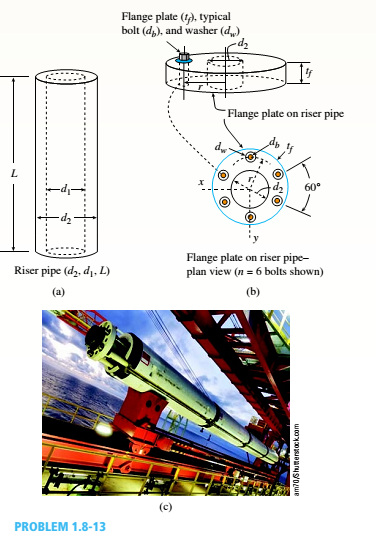
(a)
The stresses on a steel riser pipe suspended in air.
Answer to Problem 1.8.13P
The average normal stress in each bolt is
The bearing stress for each washer is
The average shear stress at each bolt location in flange is
Explanation of Solution
Given information:
Steel riser pipe length is
Write the expression for average normal stress in each bolt for steel riser pipe suspended in air.
Here, the area of the riser pipe is
Write the expression for the area of pipe.
Here, the area of pipe is
Write the expression for the area of a bolt.
Here, the diameter of bolt is
Write the expression for bearing stress for each washer.
Here, the area of a washer is
Write the expression for the washer area.
Here, the diameter of bolt is
Write the expression for average shear stress at each bolt location in flange.
Here, the thickness of flange is
Calculation:
Substitute
Substitute
Substitute
Substitute
Substitute
Substitute
Conclusion:
The average normal stress in each bolt is
The bearing stress for each washer is
The average shear stress at each bolt location in flange is
(b)
The stresses on a steel riser pipe hanging from a drill rig at sea water.
Answer to Problem 1.8.13P
The average normal stress in each bolt is
The average bearing stress beneath each washer is
The average shear stress at each bolt location in flange is
Explanation of Solution
Write the expression for average normal stress in each bolt for a steel riser pipe hanging from a drill rig in sea water.
Here, the net weight density is
Write the expression for average bearing stress beneath each washer.
Here, the area of a washer is
Write the expression for average shear stress at each bolt location in flange.
Substitute
Substitute
Substitute
Conclusion:
The average normal stress in each bolt
The average bearing stress beneath each washer
The average shear stress at each bolt location in flange
Want to see more full solutions like this?
Chapter 1 Solutions
Mechanics of Materials - Text Only (Looseleaf)


- A steel riser pipe hangs from a drill rig. Individual segments of equal length L = 50 ft are joined to get her using bolted flange plates (see figure part b). There are six bolts at each pipe segment connection. The outer and inner pipe diameters are t2= 14 in. and d1= 13 in.; flange plate thickness tf= 1.5 in.; and boll and washer diameters are db= 1.125 in. and dn. = 1.875 in. Find the number n of permissible segments of pipe based on following allowable stresses. (a) The allowable tensile stress in the pipe is 50 ksi. (b) The allowable tensile stress in a bolt is 120 ksi. Find number of segments n for two cases: pipe hanging in air and pipe hanging in seawater.arrow_forwardA square steel tube of a length L = 20 ft and width b2= 10.0 in. is hoisted by a crane (see figure). The lube hangs from a pin of diameter d that is held by the cables at points A and B. The cross section is a hollow square with an inner dimension b1= 8.5 in. and outer dimension b2= 10,0 in. The allowable shear stress in the pin is 8,700 psi. and the allowable bearing stress between the pin and the tube is 13,000 psi. Determine the minimum diameter of the pin in order to support the weight of the tube. Note: Disregard the rounded corners of the tube when calculating its weight.arrow_forwardA plane truss is subjected to loads 2P and P at joints B and C, respectively, as shown in the figure part a. The truss bars are made of two L 102 X 76 X 6.4 steel angles (see Table F-5(b): cross-sectional area or the two angles, A = 2180 mm2, and figure part b) having an ultimate stress in tension equal to 390 MPa. The angles are connected to a 12-mm-thick gusset plate at C(figure part c) with 16-mm diameter rivets; assume each rivet transfers an equal share of the member force to the gusset plate. The ultimate stresses in shear and bearing for the rivet steel are 190 MPa and 550 MPa, respectively. Determine the allowable load Pallowif a safety factor of 2.5 is desired with respect to the ultimate load that can be carried. Consider tension in the bars, shear in the rivets, bearing between the rivets and gusset plate. Disregard friction between the plates the bars, and also bearing between the rivets and the and the weight of the truss itself.arrow_forward
- Two pipe columns (AB, FC) are pin-connected to a rigid beam (BCD), as shown in the figure. Each pipe column has a modulus of E, but heights (L1or L2) and outer diameters (d1or different for each column. Assume the inner diameter of each column is 3/4 of outer diameter. Uniformly distributed downward load q = 2PIL is applied over a distance of 3L/4 along BC, and concentrated load PIA is applied downward at D. (a) Derive a formula for the displacementarrow_forwardA hollow circular tube T of a length L = 15 in. is uniformly compressed by a force P acting through a rigid plate (see figure). The outside and inside diameters of the tube are 3.0 and 2.75 in., respectively. A concentric solid circular bar B of 1.5 in. diameter is mounted inside the lube. When no load is present, there is a clearance c = 0.0I0 in. between the bar B and the rigid plate. Both bar and tube are made of steel having an c[autoplastic stress-strain diagram with E = 29 X LO3 ksi and err= 36 ksi. (a) Determine the yield load Pt- and the corresponding shortening 3yof the lube. (b) Determine the plastic load Ppand the corresponding shortening Spof the tube. (c) Construct a load-displacement diagram showing the load Pas ordinate and the shortening 5 of the tube as abscissa. Hint: The load-displacement diagram is not a single straight line in the region 0 ^ P ^ Prarrow_forwardAround brass bar of a diameter d1= 20mm has upset ends each with a diameter d2= 26 mm (see figure). The lengths of the segments of the bar are L1= 0.3 m and L2= 0.1 m. Quarter-circular fillets are used at the shoulders of the bar, and the modulus of elasticity of the brass is E = 100 GPa. If the bar lengthens by 0.12 mm under a tensile load P, what is the maximum stress ??maxin the bar?arrow_forward
- The upper deck ala foothill stadium is supported by braces, each of which transfer a load P = 160 kips to the base of a column (see figure part a). A cap plate at the bottom of the brace distributes the load P to four flange pates (:1 = I in)t hrough a pin(d, = 2 in.) to two gusset plates t8 = l.5 in.) (see figure parts b and c). Determine the following quantities. (a) The average shear stress i in the pin. (b) The average bearing stress between the flange plates and the pin and also between the gusset plates and the pin Disregard friction between the plates. Determine the following quantities. (a) The average shear stress i in the pin. (b) The average bearing stress between the flange plates and the pin and also between the gusset plates and the pin (7j )L Disregard friction between the plates.arrow_forwardTwo pipes {L, = 2.5 m and L, = 1.5 m) are joined al B by flange plales (thickness (, = 14 mm) with five bolts [dlt, = 13 mm] arranged in a circular pal tor n (see figure). Also, each pipe segment is atlaehed to a wall (at .1 and ( '. see figure! using a base plate Uh = 15 mm) and four bolts (dM, = 16 mm). All bolts are tightened until just snug. Assume £, = 110 GPa,E2 = 73 GPa,», = 0.33,andv, = 0.25. Neglect the self-weight of the pipes, and assume the pipes are in a stress-free stale initially. The cross-sectional areas of the pipes are At = 1500 mm: and A2 = (3/5)4. The ollter diameter of Pipe 1 is 60 mm. The outer diameter of Pipe 2 is equal to the inner diameter of Pipe 1. The bolt radius r = 64 mm for both base and flange plates. (a) If torque '/'is applied at .v = Lt. find an expression for reactive torques Iit and IL in terms of T. (b) Find the maximum load variable /'(i.e., Tmal) if allowable torsional stress in the two pipes is Tall0* = 65 MPa-id Draw torsional moment iTMD i and torsional displacement (TDD) diagrams. Label all key ordinales. What is '/>.ll('.' (d) Find mail, if allowable shear and bearing stresses in the base plate and flange bolts cannot be exceeded. Assume allowable stresses in shear an.: :vari:'.g I all bolls are r |Nill, = 45 MPa andtr MaK =90 MPa. (e) Remove torque Tat x — L,. Now assume the flange-plate bolt holes are misaligned by some angle ß (see figure). Find the expressions for reactive torques Rx and R2 if the pipes are twisted to align the flange-plate bolt holes, bolts are then inserted, and the pipes released. (f) What is the maximum permissible misalignment angle ß mix if allowable stresses in shear and bearing for all bolts [from part (d)] are not to be exceeded?arrow_forwardA steel riser pipe hangs from a drill rig located offshore in deep water (see figure). (a) What is the greatest length (meters) it can have without breaking if the pipe is suspended in the air and the ultimate strength (or breaking strength) is 550 MPa? (b) If the same riser pipe hangs from a drill rig at sea, what is the greatest length? (Obtain the weight densities of steel and sea water from Table M, Appendix I. Neglect the effect of buoyant foam casings on the pipe.)arrow_forward
- A large precast concrete panel for a warehouse is raised using two sets of cables at two lift lines, as shown in the figure part a. Cable 1 has a length L1 = 22 Ft, cable 2 has a length L2= 10 ft, and the distance along the panel between lift points Band D is d = 14 ft (see figure part b). The total weight of the panel is W = 85 kips. Assuming the cable lift Forces F at each lift line are about equal, use the simplified model of one half of the panel in figure part b to perform your analysis for the lift position shown. Find the required cross-sectional area AC of the cable if its breaking stress is 91 ksi and a factor of safety of 4 with respect to failure is desired.arrow_forwardA vertical pole of solid, circular cross section is twisted by horizontal forces P = 1100 lb acting at the ends of a rigid horizontal arm AB (see figure part a). The distance from the outside of the pole to the line of action of each force is c = 5.0 in. (see figure part b) and the pole height is L = 14in. (a) If the allowable shear stress in the pole is 4500 psi, what is the minimum required diameter dminof the pole? Find the torsional stiffness of the pole (kip-in./rad). Assume that G = 10,800 ksi. If two translational springs, each with stiffness k = 33 kips/in., are added at 2(75 from A and B (see figure part c), repeat part (a) to find dmin. Hint: Consider the pole and pair of springs as "springs in parallel."arrow_forwardA retaining wall 6 ft high is constructed of horizontal wood planks 2.5 in. thick (actual dimension) that are supported by vertical wood piles of a 12 in, diameter (actual dimension), as shown in the figure. The lateral earth pressure is pt=125 lb/ft2 at the top of the wall and p2= 425 lb/ft2 at the bottom. Assuming that the allowable stress in the wood is 1175 psi, calculate the maximum permissible spacing s of the piles. Find the required diameter of the wood piles so that piles and planks (f = 2.5 in.) reach the allowable stress at the same time. Hint: Observe that the spacing of the piles may be governed by the load-carrying capacity of either the planks or the piles. Consider the piles to act as cantilever beams subjected to a trapezoidal distribution of load, and consider the planks to act as simple beams between the piles. To be on the safe side, assume that the pressure on the bottom plank is uniform and equal to the maximum pressure.arrow_forward
 Mechanics of Materials (MindTap Course List)Mechanical EngineeringISBN:9781337093347Author:Barry J. Goodno, James M. GerePublisher:Cengage Learning