Concept explainers
Videos
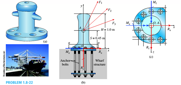
A cargo ship is tied down to marine boll arts at a number of points along its length while its cargo is unloaded by a container handling crane. Each bollard is fastened to the wharf using anchor bolts. Three cables having known tension force magnitudes F, = ll0 kN.F, = 85kN.and F, 9OkNare secured to one bollard at a point A with coordinates (0.0.45 m. 0) in the x-r-: coordinate system shown in the figure part b. Each cable force is directed at an attachment point on the ship. Force F, is directed
from point A to a point on the ship having coordinates (3 m, 9 m. 0) force F, is directed at a point with coordinates (6.5 m. 8.5 m. 2 m) and force F, is directed at a point with coordinates (8 m. 9 m. S m). The diameter of each anchor bolts is 4 24 mm.
(a) Find the reaction forces and reaction moments at the base of the bollard.
(b) Calculate the average shear stress in the anchor bolts (in the x-: plane). Assume each bolt cart ics an equal share of the total force.
Want to see the full answer?
Check out a sample textbook solution
Chapter 1 Solutions
Mechanics of Materials - Text Only (Looseleaf)


- Find support reactions at 4 and Band then use the method of joints to find all member forces. Let b = 3 m and P = 80 kN.arrow_forwardA crane boom of mass 450 leg with its center of mass at C is stabilized by two cables AQ and BQ (Ae= 304 mm2 for each cable) as shown in the figure. A load P = 20 KN is supported at point D. The crane boom lies in the y-z plane. (a) Find the tension forces in each cable: TAQand TBQ(kN}. Neglect the mass of the cables, but include the mass of the boom in addition to load P. (b) Find the average stress (s) in each cable.arrow_forwardSpace Frame ABC is clamped at A, except it is free to rotate at A about the x and y axes. Cables DC and EC support the frame at C. Force Py= - 50 lb is applied at the mid-span of AS, and a concentrated moment Mx= -20 in-lb acts at joint B. (a) Find reactions at support A. (b) Find cable tension Forces.arrow_forward
- A soccer goal is subjected to gravity loads (in the - z direction, w = 73 N/m for DG, BG, and BC; w = 29 N/m for all other members; see figure) and a force F = 200 N applied eccentrically at the mid-height of member DG. Find reactions at sup ports C, D, and H.arrow_forward.17 A mountain-bike rider going uphill applies torque T = Fd(F = l5lb, d = 4 in.) to the end of the handlebars ABCD by pulling on the handlebar extenders DE. Consider the right half of the handlebar assembly only (assume the bars are fixed at the fork at A). Segments AB and CD are prismatic with lengths L, = 2 in.andL3 = 8.5 in, and with outer diameters and thicknesses d01 = 1.25 in. 101 = 0.125 in. and d03 = O.87in.,i03 = 0.ll5in, respectively as shown. Segment BC’ of length L, = 1.2 in. however. is tapered, and outer diameter and thickness vary linearly between dimensions at B and C. Consider torsion effects only. Assume G = 4000 ksi is constant. Derive an integral expression for the angle of twist of half of the handlebar tube when it is subjected to torque T = Fd acting at the end. Evaluate ‘b1-, for the given numerical1ues.arrow_forwardA bimetallic bar (or composite bar) of square cross sec lion with dimensions 2b X lb is construe ted of two different metals having module of elasticity E2and E2(see figure). The two parts of the bar have the same cross-sectional dimensions. The bar is compressed by forces P acting through rigid end plates. T h e line of action of t he loads has an eccentricity e of such magnitude that each part of the bar is stressed uniformly in compression. (a) Determine the axial forces Ptand P2in the two parts of the bar. (b} Determine the eccentricity e of the loads. (c) Determine the ratio C|/tr2 of the stresses in the two parts of the bar.arrow_forward
- By what distance h does the cage shown in the figure move downward when the weight W is placed inside it? (See the figure.) Consider only the effects of the stretching of the cable, which has axial rigidity EA = 10,700 kN. The pulley at A has a diameter da= 300 mm and the pulley at B has a diameter dB= 150 mm. Also, the distance L1= 4.6 m, the distance L2=10.5 m, and the weight W = 22 kN. Note: When calculating the length of the cable. include the parts of the cable that go around the pulley sat A and B.arrow_forwardA uniform bar AB of weight W = 25 N is supported by two springs, as shown in the figure. The spring on the left has a stiffness k[= 300 N/m and natural length Lt=250 mm. The corresponding quantities for the spring on the right are k2= 400 N/m and L^ = 200 mm. The distance between the springs is L = 350 mm, and the spring on the right is suspended from a support that is a distance it = SO mm below the point of support for the spring on the left. Neglect the weight of the springs. (a) At what distance x from the left-hand spring (figure part a) should a load P = 18 N be placed in order to bring the bar to a horizontal position? (b) If P is now removed, what new value of k{is required so that the bar (figure part a) will hang in a horizontal position underweight If? (c) If P is removed and kt= 300 N/m. what distance b should spring ktbe moved to the right so that the bar (figure part a) will hang in a horizontal position under weight II"? (d) If the spring on the left is now replaced by two springs in series (kt= 300 N/m, kt) with overall natural length Lt= 250 mm (see figure part b). what value of k; is required so that the bar will hang in a horizontal position under weight IF?arrow_forwardA long, slender bar in the shape of a right circular cone with length L and base diameter d hangs vertically under the action of its own weight (see figure). The weight of the cone is W and the modulus of elasticity of the material is E. Derive a formula for the increase S in the length of the bar due to its own weight. (Assume that the angle of taper of the cone is small.)arrow_forward
- .15 A hitch-mounted bicycle rack is designed to carry up to four 30-lb bikes mounted on and strapped to two arms Gil (sec bike loads in the figure part a) The rack is attached to the vehicle at A and is assumed to be like a cant silkier beam A BCDGII (figure part b) The light of fixed segment AB is U = 10 lb. centered 9 in. from A (see figure part b) and the rest of the rack highs W2 = 40 lb. centered 19 in. from A. Segment ABCDG is a steel tube o(2 X 2 in. with a thickness I = 118 in. Segment BCDGII pivots about a bolt at B with a diameter d1 = 0.25 in. to allow access to the rear of the vehicle without removing the hitch rack. When in use, the rack is secured in an upright posit ion by a pin C(diameter o( pin d, = 5116 in.) (see phoo and figure part C). The of returning effect of the bikes on the rack is resisted by a force couple F h at BC. (a) Find the support reactions at A for the fully loaded rack. (b) Find forces in the bolt at B and the pin at C. (c) Find average shear stresses in both the bolt at Band the pin at C. (d) Find average bearing stresses o, in the bolt at B and the pin at C.arrow_forwardA rigid bar of weight W = SOO N hangs from three equally spaced vertical wines( length L = 150 mm, spacing a = 50 mm J: two of steel and one of aluminum. The wires also support a load P acting on the bar. The diameter of the steel wires is ds= 2 mm, and the diameter of the aluminum wire is d = A mm. a Assume £,=210 GPa and EB« 70 GPa. What load Pallowcan be supported at the mitl-point of the bar (x = a) if the allowable stress in the steel wires is 220 MPa and in the aluminum wire is 80 MPa? (See figure part (b) What is /*,Ikw» if the load is positioned at .v = all1? (See figure part a.) (c) Repeat part (b) if the second and third wires are switched as shown in the figure part b.arrow_forwardAn L-shaped reinforced concrete slab 12 Ft X 12 ft, with a 6 Ft X 6 ft cut-out and thickness t = 9.0 in, is lifted by three cables attached at O, B, and D, as shown in the figure. The cables are are combined at point Q, which is 7.0 Ft above the top of the slab and directly above the center of mass at C. Each cable has an effective cross-sectional area of Ae= 0.12 in2. (a) Find the tensile force Tr(i = 1, 2, 3) in each cable due to the weight W of the concrete slab (ignore weight of cables). (b) Find the average stress ov in each cable. (See Table I-1 in Appendix I for the weight density of reinforced concrete.) (c) Add cable AQ so that OQA is one continuous cable, with each segment having Force T, which is connected to cables BQ and DQ at point Q. Repeat parts (a) and (b). Hini: There are now three Forced equilibrium equations and one constrain equation, T1= T4.arrow_forward
 Mechanics of Materials (MindTap Course List)Mechanical EngineeringISBN:9781337093347Author:Barry J. Goodno, James M. GerePublisher:Cengage Learning