
CONTROL SYSTEMS ENGINEERING
7th Edition
ISBN: 2819770197050
Author: NISE
Publisher: WILEY
expand_more
expand_more
format_list_bulleted
Concept explainers
Videos
Textbook Question
Chapter 1, Problem 3P
An aircraft's attitude varies in roll, pitch, and yaw as defined in Figure Pl .2. Draw a functional block diagram for a closed-loop system that stabilizes the roll as follows: The system measures the actual roll angle with agyro and compares the actual roll angle w ith the desired roll angle. The ailerons respond to the roll-angle error by undergoing an angular deflection. The aircraft responds to this angular deflection, producing a roll angle rate. Identify the input and output transducers, the controller, and the plant. Further, identify the nature of each signal. [Section 1.4: Introduction to a Case Study]
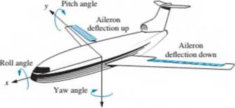
FIGURE Pl.2 Aircraft attitude defined
Expert Solution & Answer
Want to see the full answer?
Check out a sample textbook solution
Students have asked these similar questions
Statics; Diagram and working.
Needs Complete typed solution with 100 % accuracy.
The governor is a mechanically-controlled feedback device which maintains the speed
of an engine within permissible range whenever there is a variation of load. There is
various type of governor in the industry as shown in Q6(a). With the aid of a diagram
of forces acting on the governor at the equilibrium, explain the limitations of a Watt
governor and how these are rectified in the Porter governor.
Figure Q6(a): Various types of governor.
Chapter 1 Solutions
CONTROL SYSTEMS ENGINEERING
Ch. 1 - Prob. 1RQCh. 1 - Prob. 2RQCh. 1 - Prob. 3RQCh. 1 - Prob. 4RQCh. 1 - State one condition under which the error signal...Ch. 1 - Prob. 6RQCh. 1 - Name two advantages of having a computer in the...Ch. 1 - Name the three major design criteria for control...Ch. 1 - Prob. 9RQCh. 1 - Physically, what happens to a system that is...
Ch. 1 - Instability is attributable to what pan of the...Ch. 1 - Describe a typical control system analy sis task.Ch. 1 - Describe a typical control system design task.Ch. 1 - Prob. 14RQCh. 1 - Name three approaches to the mathematical modeling...Ch. 1 - Briefly describe each of your answers to Question...Ch. 1 - Prob. 1PCh. 1 - Prob. 2PCh. 1 - An aircraft's attitude varies in roll, pitch, and...Ch. 1 - We can build a control system that will...Ch. 1 - Prob. 5PCh. 1 - During a medical operation an anesthesiologist...Ch. 1 - Prob. 7PCh. 1 - Prob. 8PCh. 1 - The human eye has a biological control system that...Ch. 1 - A Segway ®5 Personal Transporter (PT) (Figure Pl...Ch. 1 - In humans, hormone levels, alertness, and core...Ch. 1 - Tactile feedback is an important component in the...Ch. 1 - Prob. 13PCh. 1 - Moored floating platforms are subject to external...Ch. 1 - In the Case Study of Section 1.4. an antenna...Ch. 1 - Figure Pl.5 shows the topology of a photo-voltaic...Ch. 1 - Prob. 17PCh. 1 - Prob. 18PCh. 1 - Prob. 19PCh. 1 - Prob. 20PCh. 1 - Prob. 21PCh. 1 - Contol of HIV/AIDS. As of 2012. the number of...Ch. 1 - Prob. 23PCh. 1 - Parabolic trough collector. A set of parabolic...
Knowledge Booster


Learn more about
Need a deep-dive on the concept behind this application? Look no further. Learn more about this topic, mechanical-engineering and related others by exploring similar questions and additional content below.Similar questions
- 2. A model for an airplane's pitch loop is shown below. Find the range of K that will keep the system stable. Can the system ever be unstable for positive values of K? Controller Aircraft dynamics Commanded pitch angle + K(s + 1) Pitch angle s + 10 s2 + 0.6s + 9 (s + 4.85) 1 Gyroarrow_forwardwrite solutions pleasearrow_forwardTask 1): The quarter-car model of a vehicle suspension and its free body diagram are shown in Figure 1. In this simplified model, the masses of the wheel, tire, and axle are neglected, and the mass m represents one-fourth of the vehicle mass. The spring constant k models the elasticity of both the tire and the suspension spring. The damping constant c models the shock absorber. The equilibrium position of m when y=0 is x=0. The road surface displacement y(t) can be derived from the road surface profile and the car's speed. a) Draw free body diagram (FBD) and derive the equation of motion of m with y(t) as the input, and obtain the transfer function. Body m 1 Suspension Road k Datum level Figure 1 Dynamic Analysis and Control If assume: m=250 kg k=10000, 30000, 50000 N/m c=1000, 2000, 3000 N.s/m b) Plot magnification ratio vs frequency ratio (r=0-4) diagrams for the parameters given above (you can draw the three curves in one diagram for three different k values and do the same for the…arrow_forward
- Answer the question based on the space mission “IMANI FORD”arrow_forwardMy registration number is 18arrow_forwardFrame the three equations and find the constants of the Freudenstein's equation for the given data. A four-bar mechanism is to be designed in a automotive industry to perform automation of packaging. The given input angles and the required output angles are given below. O, is along 03 is 40° greater than 02 Input angle, 0 02 is 30° greater than 01 positive x axis Pi is 20° lesser than P2 Output angle, O P 2 is same as 03 P3 = 02arrow_forward
- 2. Determine the transfer function from aileron deflection to roll rate in a F-104A aircraft. Assume the airplane is flying at sea level at a speed of 87m/sec. The F104A has the following aerodynamic and geometric data: Mass moment of inertia about the roll axis: I, = 4676kg m? Roll damping: 6079N m/rad/sec Roll moment from aileron control input: 380N m/degarrow_forwardsubject: vibrationarrow_forwardPlease explain all subparts. I will really upvotearrow_forward
- What are the Lagrange equations of the PR manipulator?arrow_forwardPlease help me solve no. 2 below. Please provide a clear and readable solution. Thanks in advance!!! The course subject is Feedback and Control System. NOTE: The lesson is ROTATIONAL MECHANICAL SYSTEMS.arrow_forwardHello, i am asked to create my own statics problem, here are the specifications. Thank you very much!!!!arrow_forward
arrow_back_ios
SEE MORE QUESTIONS
arrow_forward_ios
Recommended textbooks for you
 Elements Of ElectromagneticsMechanical EngineeringISBN:9780190698614Author:Sadiku, Matthew N. O.Publisher:Oxford University Press
 Mechanics of Materials (10th Edition)Mechanical EngineeringISBN:9780134319650Author:Russell C. HibbelerPublisher:PEARSON
 Thermodynamics: An Engineering ApproachMechanical EngineeringISBN:9781259822674Author:Yunus A. Cengel Dr., Michael A. BolesPublisher:McGraw-Hill Education
 Control Systems EngineeringMechanical EngineeringISBN:9781118170519Author:Norman S. NisePublisher:WILEY
 Mechanics of Materials (MindTap Course List)Mechanical EngineeringISBN:9781337093347Author:Barry J. Goodno, James M. GerePublisher:Cengage Learning
 Engineering Mechanics: StaticsMechanical EngineeringISBN:9781118807330Author:James L. Meriam, L. G. Kraige, J. N. BoltonPublisher:WILEY
Elements Of Electromagnetics
Mechanical Engineering
ISBN:9780190698614
Author:Sadiku, Matthew N. O.
Publisher:Oxford University Press
Mechanics of Materials (10th Edition)
Mechanical Engineering
ISBN:9780134319650
Author:Russell C. Hibbeler
Publisher:PEARSON
Thermodynamics: An Engineering Approach
Mechanical Engineering
ISBN:9781259822674
Author:Yunus A. Cengel Dr., Michael A. Boles
Publisher:McGraw-Hill Education
Control Systems Engineering
Mechanical Engineering
ISBN:9781118170519
Author:Norman S. Nise
Publisher:WILEY
Mechanics of Materials (MindTap Course List)
Mechanical Engineering
ISBN:9781337093347
Author:Barry J. Goodno, James M. Gere
Publisher:Cengage Learning
Engineering Mechanics: Statics
Mechanical Engineering
ISBN:9781118807330
Author:James L. Meriam, L. G. Kraige, J. N. Bolton
Publisher:WILEY
Dynamics - Lesson 1: Introduction and Constant Acceleration Equations; Author: Jeff Hanson;https://www.youtube.com/watch?v=7aMiZ3b0Ieg;License: Standard YouTube License, CC-BY