
Basic Engineering Circuit Analysis
11th Edition
ISBN: 9781118539293
Author: J. David Irwin, R. Mark Nelms
Publisher: WILEY
expand_more
expand_more
format_list_bulleted
Concept explainers
Videos
Textbook Question
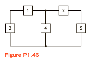
Chapter 1, Problem 46P
In the circuit in Fig.
Expert Solution & Answer

Learn your wayIncludes step-by-step video

schedule02:18
Students have asked these similar questions
Find the current in i in the electrical circuit below
54 k0
SV
a. 15uA
Ob.20u A
c.25JA
Od25pA
A Moving to another question will save this response.
mc021-1jpg:
mc030-2jpg
mc024-3 pg
Verified
Venfied
1:07
2021
Pr
EN
K7
Q2. For the network in next Figure, determine R1:
24 2
Ry= 100
Chapter 1 Solutions
Basic Engineering Circuit Analysis
Ch. 1 - If the current in an electric conductor is 2.4 A,...Ch. 1 - Determine the time interval required for a 12�A...Ch. 1 - A lightning bolt carrying 30,000 A lasts for 50...Ch. 1 - If a 12-V battery delivers 100 J in 5 s, find (a)...Ch. 1 - The current in a conductor is 1.5 A. How many...Ch. 1 - If 60 C of charge pass through an electric...Ch. 1 - Determine the number of coulombs of charge...Ch. 1 - Five coulombs of charge pass through the element...Ch. 1 - The current that enters an element is shown in...Ch. 1 - The charge entering the positive terminal of an...
Ch. 1 - The charge entering the positive terminal of an...Ch. 1 - Prob. 12PCh. 1 - The power absorbed by the BOX in Fig. Pl. 13 is...Ch. 1 - The power absorbed by the BOX in Fig. Pl. 14 is...Ch. 1 - The energy absorbed by the BOX in Fig. P1.15 is...Ch. 1 - The charge that enters the BOX in Fig. P1.16 is...Ch. 1 - The energy absorbed by the BOX in Fig. Pl. 17 is...Ch. 1 - The charge entering the upper terminal of the BOX...Ch. 1 - The energy absorbed by the BOX in Fig. Pl. 19 is...Ch. 1 - Determine the amount of power absorbed or supplied...Ch. 1 - Calculate the power absorbed by element A in Fig....Ch. 1 - Calculate the power supplied by element A in Fig....Ch. 1 - Element A in the diagram in Fig. PI .23 absorbs 30...Ch. 1 - Element B in the diagram in Fig. P1.24 supplies 60...Ch. 1 - Element B in the diagram in Fig. PI .25 supplies...Ch. 1 - Element B in the diagram in Fig. Pl.26 supplies 72...Ch. 1 - (a) In Fig. Pl.27 (a), P1=36W. Is element 2...Ch. 1 - Two elements are connected in series, as shown in...Ch. 1 - Element 2 in Fig. Pl.29 absorbed 32W. Find the...Ch. 1 - Choose Is such that the power absorbed by element...Ch. 1 - Find the power that is absorbed or supplied by the...Ch. 1 - Find the power that is absorbed or supplied by the...Ch. 1 - Compute the power that is absorbed or supplied by...Ch. 1 - Find the power that is absorbed or supplied by...Ch. 1 - Find Ix in the network in Fig. P1.35.Ch. 1 - Prob. 36PCh. 1 - Find the power absorbed or supplied by element 1...Ch. 1 - Find the power absorbed or supplied by element 3...Ch. 1 - Find the power absorbed or supplied by element 1...Ch. 1 - Find Vx in the network in Fig. P1.40 using...Ch. 1 - Find Ix in the circuit in Fig. P1.41 using...Ch. 1 - Is the source Vs in the network in Fig. P1.42...Ch. 1 - Find I0 in the network in Fig. P1.43 using...Ch. 1 - Calculate the power absorbed by each element in...Ch. 1 - Calculate the power absorbed by each element in...Ch. 1 - In the circuit in Fig. P1.46, element 1 absorbs 40...
Additional Engineering Textbook Solutions
Find more solutions based on key concepts
For each configuration in Fig. 6.64, find the voltage sources and/or resistors elements (individual elements, n...
Introductory Circuit Analysis (13th Edition)
Using only one OP AMP, design a circuit that realizes the following equation: vO=5v13.3V
ANALYSIS+DESIGN OF LINEAR CIRCUITS(LL)
The switch in the bottom loop of Fig. P6.1 is closed at t = 0 and then opened at a later time t1. What is the d...
Fundamentals of Applied Electromagnetics (7th Edition)
Use the current-division principle to calculate i1 and i2 in Figure P2.37. Figure P2.3
Electrical Engineering: Principles & Applications (7th Edition)
In the circuit shown in Fig. P 7.26, both switches operate together; that is, they either open or close at the ...
Electric Circuits (10th Edition)
For the circuit shown, use the node-voltage method to find v1, v2, and i1.
How much power is delivered to the c...
Electric Circuits. (11th Edition)
Knowledge Booster


Learn more about
Need a deep-dive on the concept behind this application? Look no further. Learn more about this topic, electrical-engineering and related others by exploring similar questions and additional content below.Similar questions
- Solve the following Numerical problems a. What is the Output Voltage of a battery that expends 7.2J of energy in moving 1C of charge? b. A 50-ohm load dissipates 200W of power. How much is the voltage and current across the load? c. If one branch of a 120-V power line is protected by a fuse of 20-A. Will the fuse carry 10-Ohm load? d. If total resistance of a series circuit is 280-Ohm. If one of the resistance is 160-Ohm. What is the sum of other two resistances?arrow_forwardA farm has a monthly consumption of 400 kWh, where all energy consumed is generated through of biogas. Consider that 1m3 of biogas is equivalent to 1.4 kWh. In the calculation, consider that the raw material of the biodigester will consist of swine manure that produces 4 kg of manure each, with retention time in the biodigester for 45 days. What is the daily biogas consumption to serve this residence and how much waste is needed daily?arrow_forwardSolve for: a. Id (atleast 4 decimal place) b. Vgs c. Vd (Atleast 3 decimal value) d. Vs a. Id-Blank 1 mA b. Vgs-Blank 2V c. Vd-Blank 3V d. Vs-Blank 4 V Blank 1 Add your answer Blank 2 Add your answer Blank 3 Add your answer Blank 4 Add your answer c). 1 MQ 1.5V. 12 V 1.210 Ing Vaso oss = 12 mA V₂ =-4Varrow_forward
- The circuit shown below is an example of a simple voltage regulator. Determine the current through R1 in mA. Assume the following values for the resistors: R1 = 14 k0, R2 = 12 k0. Express your answer using three decimal places. Assume the opamp is ideal and Q1's ß is infinity. Q1 VCC Vref NPN U1 OUT 20V 1.2V R1 R2 wwarrow_forwardIn the following circuit R = 12 ohms, C = 4 micro-farads, and C2 = 10 micro-farads. After some time with the battery connected, the current through the battery is 7 amps. At that time, the battery is removed (but the circuit is closed). The stored energy in C2 0.9 micro-seconds after the battery has been removed is 114 micro-joules. What was the power output of the battery, in Watts, at the time it was removed? R C1 C2 Varrow_forwardDetermine total charge entering the terminal between t-3 s and t-6 s if the current passing the terminal is i(t)=10t A, q(0)= 30 C. Please show all calculation steps. Please upload your solution in image format. REMARK For upload image question-type, you need to capture the image of your solution and upload your answer in Author using phone. The image automatically saved once successfully uploaded. Refer to the image below for a clear guidance. ClHO here to uploed your Type G &OF YOU Can upicad many time of solutionarrow_forward
- 9 TPH material is heated in a oil fired furnace. The temperature of material is increased by 1300°C. Oil used per hour is 700 litres, specific gravity oil is 0.95 and its net calorific value is 9500 kcal/kg. Find thermal efficiency of the furnace if specific heat of material is 0.12 kcal/kg °C.arrow_forwardFor the element in the figure below, V₁ = 17 V. What is v₂ in volts (V)? Varrow_forwardIf the voltage Vx is 11.95 V, what will be the measured voltage if we take the output from the anode of D3 to the positive terminal of C1? (use 1st assumption - all ideal, answer in 2 Decimal place). Express your answer in V. No units required. Vx C1 D1 C2 H6 D2 C3 D3 C4 H6 D4arrow_forward
- Use the following constants if necessary. Coulomb constant, k = 8.987 x 10° N - m² /C2. Vacuum permitivity, co = 8.854 x 10 12 F/m. Magnetic Permeability of vacuum, Ho = 12.566370614356 x 10-' H/m. Magnitude of the Charge of one electron, e = -1.60217662 × 10⁻¹⁹ C. Mass of one electron, me = 9.10938356 x 10 31 kg. Unless specified otherwise, each symbol carries their usual meaning. For example, µC means micro coulomb. a R5 R3 e R9 R, R6 R8 Ry K Suppose you have the following circuit diagram. Here R1 =1.1 kN, R2 = 3.3 kN, R3 = 2.2 kN, R4 = 22 kN, R5 = 22 kN, Rg = 11 kN, R7 = 11 kN, Rg = 11 kN, R9 = 1.1 kN are the resistances on the circuit where kN stands for kilo ohm. The electromotive forces of the batteries are & = 5 volts and Ez = 3 volts. a) Calculate Rik. the resistance equivalent to R5, Re, R7, Rg and R9 between the terminals b and k. Value of Rhk Give your answer to at least two significance digits. Ω b) Calculate the current through R1.arrow_forwardCalculate the approximate output power of a PV cell with the area of 10cm*10Cm? a. 150W b. 1.5W c. 0.15W d. 15Warrow_forwardPlease calculate the equivalent resistance? 42.0 Q www 75.09 M a. 14.82 Ohm b. 117.03 Ohm c33.03 Ohm d. 150 Ohm e. 59.92 Ohm 33.0 22 MWarrow_forward
arrow_back_ios
SEE MORE QUESTIONS
arrow_forward_ios
Recommended textbooks for you
 Introductory Circuit Analysis (13th Edition)Electrical EngineeringISBN:9780133923605Author:Robert L. BoylestadPublisher:PEARSON
 Delmar's Standard Textbook Of ElectricityElectrical EngineeringISBN:9781337900348Author:Stephen L. HermanPublisher:Cengage Learning
 Programmable Logic ControllersElectrical EngineeringISBN:9780073373843Author:Frank D. PetruzellaPublisher:McGraw-Hill Education
 Fundamentals of Electric CircuitsElectrical EngineeringISBN:9780078028229Author:Charles K Alexander, Matthew SadikuPublisher:McGraw-Hill Education
 Electric Circuits. (11th Edition)Electrical EngineeringISBN:9780134746968Author:James W. Nilsson, Susan RiedelPublisher:PEARSON
 Engineering ElectromagneticsElectrical EngineeringISBN:9780078028151Author:Hayt, William H. (william Hart), Jr, BUCK, John A.Publisher:Mcgraw-hill Education,
Introductory Circuit Analysis (13th Edition)
Electrical Engineering
ISBN:9780133923605
Author:Robert L. Boylestad
Publisher:PEARSON
Delmar's Standard Textbook Of Electricity
Electrical Engineering
ISBN:9781337900348
Author:Stephen L. Herman
Publisher:Cengage Learning
Programmable Logic Controllers
Electrical Engineering
ISBN:9780073373843
Author:Frank D. Petruzella
Publisher:McGraw-Hill Education
Fundamentals of Electric Circuits
Electrical Engineering
ISBN:9780078028229
Author:Charles K Alexander, Matthew Sadiku
Publisher:McGraw-Hill Education
Electric Circuits. (11th Edition)
Electrical Engineering
ISBN:9780134746968
Author:James W. Nilsson, Susan Riedel
Publisher:PEARSON
Engineering Electromagnetics
Electrical Engineering
ISBN:9780078028151
Author:Hayt, William H. (william Hart), Jr, BUCK, John A.
Publisher:Mcgraw-hill Education,
Kirchhoff's Rules of Electrical Circuits; Author: Flipping Physics;https://www.youtube.com/watch?v=d0O-KUKP4nM;License: Standard YouTube License, CC-BY