
EBK PRINCIPLES OF FOUNDATION ENGINEERIN
8th Edition
ISBN: 8220100547058
Author: Das
Publisher: CENGAGE L
expand_more
expand_more
format_list_bulleted
Concept explainers
Videos
Textbook Question
Chapter 10, Problem 10.14P
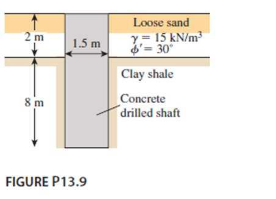
Figure P13.9 shows a drilled shaft extending into clay shale. Given: qu (clay shale) = 1.81 MN/m2. Considering the socket to be rough, estimate the allowable load-carrying capacity of the drilled shaft. Use FS = 4. Use the Zhang and Einstein procedure.
Expert Solution & Answer
Want to see the full answer?
Check out a sample textbook solution
Students have asked these similar questions
A 20 mm diameter hole is drilled on the centerline of a steel strap 50 mm wide by 5 mm thick,
subjected to an axial pull P = 10 kN. Determine the approximate maximum unit stress adjacent to the
hole.
Hint: This is a stress concentration question. The first step is to calculate the K value.
Select one:
O a. 0.1 kN/mm?
b. 0.0733 kN/mm?
c. 0.146 kN/mm2
Earth Sciences
Downward force is 4000 kg and rotational force is 3000 kg. Contact surface area (cross sectional area) is 100 cm2. Also, the rock sample (diameter: 20 cm) is tested by a uniaxial compressive strength machine and the sample was cracked at 30000 kg. Answer the following questions:a. Find the resultant force acting on the rock formation.b. Find the bearing strength of the rock drilled.c. Can we drill under these circumstances?
The boring bar of a boring machine is 25 mm in
diameter. During operation, the bar gets twisted
though 0.01 radians and is subjected to a shear
stress of 42 N/mm², The length of the bar is
(Taking G = 0.84 105 N/mm²)
Chapter 10 Solutions
EBK PRINCIPLES OF FOUNDATION ENGINEERIN
Knowledge Booster


Learn more about
Need a deep-dive on the concept behind this application? Look no further. Learn more about this topic, civil-engineering and related others by exploring similar questions and additional content below.Similar questions
- A free-headed drilled shaft is shown in Figure P13.10. Let Qg = 260 kN, Mg = 0, = 17.5 kN/m3, = 35, c' = 0, and Ep = 22 106 kN/m2. Determine a. The ground line deflection, xo b. The maximum bending moment in the drilled shaft c. The maximum tensile stress in the shaft d. The minimum penetration of the shaft needed for this analysisarrow_forwardA 3 ft diameter straight drilled shaft is shown in Figure P13.7. Determine the load-carrying capacity of the drilled shaft with FS = 3. Take / as 0.8 for the sand.arrow_forwardFor the drilled shaft described in Problem 19.7, estimate the total elastic settlement at working load. Use Eqs. (18.45), (18.47), and (18.48). Assume that Ep = 20 106 kN/m2, s = 0.3, Es = 12 103 kN/m2, = 0.65 and Cp = 0.03. Assume 80% mobilization of skin resistance at working load. (See Part c of Problem 19.7) 19.7 Figure 19.16 shows a drilled shaft without a bell. Here, L1 = 6 m, L2 = 7 m, Ds = 1.5 m, cu(1) = 50 kN/m2, and cu(2) = 75 kN/m2. Find these values: a. The net ultimate point bearing capacity. Use Eqs. (19.23) and (19.24) b. The ultimate skin resistance. Use Eqs. (19.26) and (19.28) c. The working load, Qw (FS = 3) FIG. 19.16arrow_forward
- Determine the ultimate load-carrying capacity of the drilled shaft shown in Figure P13.4, using the Reese and ONeill (1989) method.arrow_forwardA hydraulic punch press is used to punch a slot in a 0.70-in.-thick plate, as illustrated in the figure. If the plate shears at a stress of 30 ksi, determine the minimum force P required to punch the slot. Punch Answer: P = Slug Plate +0.75 in. 2.00 in. Plan view of slug kips +arrow_forward90 MPa For the shown 2D stress element, sketch Mohr circle then, use Mohr circle to find the normal and shear stresses at a point on the indicated inclined plane. 105 MPa 140° 30 MPa Verify your results (ơn, Tnt) using stress transformation eqns. Illustrate the following on Mohr circle: center of Mohr Circle, reference point A, principle stresses, max in-plane shear stress, inclined plane, orientation of inclined plane) :)arrow_forward
- Show solution. The answer must be A. 36.87 B. 14arrow_forward60 mm. PA A B 2.0052 2.1298 2.3067 2.4844 2.5111 2.1933 r = 30 mm 120 mm 800 mm r = 30 mm 200 mm 60 mm P D 200 mm If a 40 mm diameter hole were to be drilled into the center of the bar shown between points Band C, determine the stress concentration factor for the hole.arrow_forwardQ3) You are in charge of drilling operations in a sedimentary basin. The figure bellow gives the setting. Prior to drilling you have performed a numerical analysis. The table below states the necessary information at the bottom of the shale layer and at the top of the sandstone layer. Assume hydrostatic pore pressure throughout the reservoir. Stress results from your numerical models at 2250m: To [MPa] Rock layer Sy [MPa] S [MPa] S, [MPa] [deg] So [MPa] Shale Sandstone 55.2 55.2 65 40 30 20 10 0.25 30 25 30 10 5 0.25 planned wellpath Shale thickness- 2250m Sandstone: thidkness 250m A. Your drilling crew on the rig wants to drill with a setting P-Po through the shale. Will you approve this and give permission? Prove your decision by calculating the necessary stresses and show a Mohr Circle construction so that the driller can understand your reason. If unsafe, which borehole failure mechanism do we expect? ; B. Should they increase, decrease P, or stay with P=Po? Why? C. Determine the…arrow_forward
arrow_back_ios
SEE MORE QUESTIONS
arrow_forward_ios
Recommended textbooks for you
 Principles of Foundation Engineering (MindTap Cou...Civil EngineeringISBN:9781337705028Author:Braja M. Das, Nagaratnam SivakuganPublisher:Cengage Learning
 Fundamentals of Geotechnical Engineering (MindTap...Civil EngineeringISBN:9781305635180Author:Braja M. Das, Nagaratnam SivakuganPublisher:Cengage Learning
 Principles of Foundation Engineering (MindTap Cou...Civil EngineeringISBN:9781305081550Author:Braja M. DasPublisher:Cengage Learning
 Principles of Geotechnical Engineering (MindTap C...Civil EngineeringISBN:9781305970939Author:Braja M. Das, Khaled SobhanPublisher:Cengage Learning
Principles of Foundation Engineering (MindTap Cou...
Civil Engineering
ISBN:9781337705028
Author:Braja M. Das, Nagaratnam Sivakugan
Publisher:Cengage Learning
Fundamentals of Geotechnical Engineering (MindTap...
Civil Engineering
ISBN:9781305635180
Author:Braja M. Das, Nagaratnam Sivakugan
Publisher:Cengage Learning
Principles of Foundation Engineering (MindTap Cou...
Civil Engineering
ISBN:9781305081550
Author:Braja M. Das
Publisher:Cengage Learning
Principles of Geotechnical Engineering (MindTap C...
Civil Engineering
ISBN:9781305970939
Author:Braja M. Das, Khaled Sobhan
Publisher:Cengage Learning
Types of Foundation in building construction in detail - Civil Engineering Videos; Author: Civil Engineers;https://www.youtube.com/watch?v=7sl4KuM4UIE;License: Standard YouTube License, CC-BY
Types of Foundation || Foundation Engineering; Author: Civil Engineering;https://www.youtube.com/watch?v=AFLuAKGhanw;License: Standard Youtube License