
Principles of Foundation Engineering, SI Edition
8th Edition
ISBN: 9781305446298
Author: Braja M. Das
Publisher: Cengage Learning US
expand_more
expand_more
format_list_bulleted
Concept explainers
Videos
Textbook Question
Chapter 10, Problem 10.15P
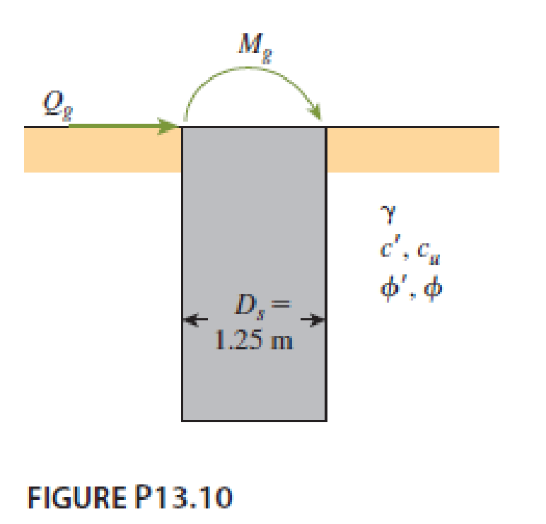
A free-headed drilled shaft is shown in Figure P13.10. Let Qg = 260 kN, Mg = 0, γ = 17.5 kN/m3, ϕ′ = 35°, c' = 0, and Ep = 22 × 106 kN/m2. Determine
- a. The ground line deflection, xo
- b. The maximum bending moment in the drilled shaft
- c. The maximum tensile stress in the shaft
- d. The minimum penetration of the shaft needed for this analysis
Expert Solution & Answer
Want to see the full answer?
Check out a sample textbook solution
Students have asked these similar questions
A free-headed drilled shaft, shown in Figure 4, has an elastic modulus, Ep = 20,000 MPa.
M, = 880 kN m
Q = 245 kN,
Sand
at = 19 kN/m3
O' = 34°
1.2 m
Figure 4
(a) Determine the ground line deflection, x.
Refer to Figure 11.26b. For the drilled shaft with bell, given:Thickness of active zone, Z = 9 mDead load = 1500 kN Live load = 300 kNDiameter of the shaft, Ds = 1 mZero swell pressure for the clay in the active zone = 600 kN/m2Average angle of plinth-soil friction, Φ'ps = 20°Average undrained cohesion of the clay around the bell = 150 kN/m2. Determine the diameter of the bell, Db. A factor of safety of 3 against uplift is required with the assumption that dead load plus live load is equal to zero.
Problem II. The figure below shows the cross-section of a thin-walled shaft subjected to a torque MT = 100 kN-m
If a = 200 mm, t = 20 mm, and G = 77.2 GPa,
t
t
t
2a
2a
a) Determine the shear stress in semi-circle portion of the profile.
b) Compute the maximum torque that can be applied if the allowable shear stress is 200 MPa
Chapter 10 Solutions
Principles of Foundation Engineering, SI Edition
Knowledge Booster


Learn more about
Need a deep-dive on the concept behind this application? Look no further. Learn more about this topic, civil-engineering and related others by exploring similar questions and additional content below.Similar questions
- Figure P13.9 shows a drilled shaft extending into clay shale. Given: qu (clay shale) = 1.81 MN/m2. Considering the socket to be rough, estimate the allowable load-carrying capacity of the drilled shaft. Use FS = 4. Use the Zhang and Einstein procedure.arrow_forward3. The A-36 steel drill shaft of an oil well extends 12000 ft into the ground. Assuming that the pipe used to drill the well is suspended freely from the derrick at A, determine the maximum average normal stress in each pipe string and the elongation of its end D with respect to the fixed end at A. The shaft consists of three different sizes of pipe, AB, BC, and CD, each having the length, weight per unit length, and cross-sectional area indicated. AAB= 2.50 in.² WAB= 3.2 lb/ft ABC= 1.75 in? WBC= 2.8 lb/ft ACD= 1.25 in.² WCD= 2.0 lb/ft B C D 5000 ft 5000 ft 2000 ftarrow_forwardEarth Sciences Downward force is 4000 kg and rotational force is 3000 kg. Contact surface area (cross sectional area) is 100 cm2. Also, the rock sample (diameter: 20 cm) is tested by a uniaxial compressive strength machine and the sample was cracked at 30000 kg. Answer the following questions:a. Find the resultant force acting on the rock formation.b. Find the bearing strength of the rock drilled.c. Can we drill under these circumstances?arrow_forward
- A compound shaft is shown. Segment (1) has an outside radius of 100 mm and thickness of wall is 10 mm. Segment (2) has an outside diameter dimension of 150mm and a wall thickness of 10 mm. The compound shaft is subjected to torques TB = 42 kN-m and TC = 18 kN-m. Evaluate the maximum shear stress magnitude in each shaft segment. Answer in MPaarrow_forwardFor the drilled shaft described in Problem 19.7, estimate the total elastic settlement at working load. Use Eqs. (18.45), (18.47), and (18.48). Assume that Ep = 20 106 kN/m2, s = 0.3, Es = 12 103 kN/m2, = 0.65 and Cp = 0.03. Assume 80% mobilization of skin resistance at working load. (See Part c of Problem 19.7) 19.7 Figure 19.16 shows a drilled shaft without a bell. Here, L1 = 6 m, L2 = 7 m, Ds = 1.5 m, cu(1) = 50 kN/m2, and cu(2) = 75 kN/m2. Find these values: a. The net ultimate point bearing capacity. Use Eqs. (19.23) and (19.24) b. The ultimate skin resistance. Use Eqs. (19.26) and (19.28) c. The working load, Qw (FS = 3) FIG. 19.16arrow_forwardExample : Figure shows bellow a drilled shaft without a bell Assume the folowing values : L1 =6 m Cu(1) = 50 KN/m L2 = 7 m Cu2) = 75 KN/m? Ds = 1.5m Determine : The net ultimate point bearing capacity by use general equation. b. The ultimate skin friction by use general equation. The working load, Qw, factor of safety = 3 a. C.arrow_forward
- A 20 mm diameter hole is drilled on the centerline of a steel strap 50 mm wide by 5 mm thick, subjected to an axial pull P = 10 kN. Determine the approximate maximum unit stress adjacent to the hole. Hint: This is a stress concentration question. The first step is to calculate the K value. Select one: O a. 0.1 kN/mm? b. 0.0733 kN/mm? c. 0.146 kN/mm2arrow_forwardA hollow circular tube is subjected to a tension force of 30 KN, a tensile stress of 20 MPa was recorded.lf the outer diameter of the tube is 100 mm, the inner diameter will be eqaual to. a. 93.95 mm O b. 89.95 mm C. 85.95 mm o d. 91.95 mmarrow_forwardThe same torque is applied to two tubes with identical metal sheets, determine the ratio of square/ circle of the shear stresses. Given: r = 16 mm, %3D S = 17 mm, and t = 2.80 mm. %3D トarrow_forward
- Hint: The problem is 10.10 taken from the book " introductory to mining engineering " written by "Howard L.Hartman" A single rectangular opening 10 ft in height is driven in rock having strengths of fc=18000 lb/in2 and ft= 1500 lb/in2. Rock specific gravity is 2.3. The opening is located at a depth of 2000 ft in a stress field of no lateral pressure and has a fillet ratio of 1/6. (a). Determine if the opening will fail when its width is 20 ft ? (b). What is the maximum safe width of the opening?.A single rectangular opening 10 ft (3.0 m) in height is driven in rock having strengths of fc = 18,000 lb/in2 (124 MPa) and ft=1500 lb/in2. (10.3 MPa).Rock specific gravity is 2.3.The opening is located at depth of 2000 ft (610 m) in a stress field of no lateral pressure and has a fillet ratio of 1/6 .a. Determine if the opening will fail when its width is 20 ft (6.1 m).b. Is there any benefit to reducing the width to 10 ft (3.0 m)? To 5 ft (1.5 m)?c. What is the maximum safe width of opening?arrow_forwardThe following data were obtained in a direct shear test. Normal pressure =20kN/m 2 , shear stress on the failure plane =16kN/m 2 . Angle of internal friction =20 ∘ , cohesion =8kN/m2. Represent the data by Mohr's Circle (by plotting) and show the principal stresses and the direction of the principal planes on the plotarrow_forwardA 6-kN-m torque is applied to a hollow shaft having the cross section shown. Neglecting the effect of stress concentrations, determine the shearing stress at points a and b. 100 mm 50 mm 8 mm b 5 mm 5 mm The shearing stresses at points a and bare MPa and MPa, respectively.arrow_forward
arrow_back_ios
SEE MORE QUESTIONS
arrow_forward_ios
Recommended textbooks for you
 Principles of Foundation Engineering (MindTap Cou...Civil EngineeringISBN:9781337705028Author:Braja M. Das, Nagaratnam SivakuganPublisher:Cengage Learning
 Principles of Foundation Engineering (MindTap Cou...Civil EngineeringISBN:9781305081550Author:Braja M. DasPublisher:Cengage Learning
 Fundamentals of Geotechnical Engineering (MindTap...Civil EngineeringISBN:9781305635180Author:Braja M. Das, Nagaratnam SivakuganPublisher:Cengage Learning
Principles of Foundation Engineering (MindTap Cou...
Civil Engineering
ISBN:9781337705028
Author:Braja M. Das, Nagaratnam Sivakugan
Publisher:Cengage Learning
Principles of Foundation Engineering (MindTap Cou...
Civil Engineering
ISBN:9781305081550
Author:Braja M. Das
Publisher:Cengage Learning
Fundamentals of Geotechnical Engineering (MindTap...
Civil Engineering
ISBN:9781305635180
Author:Braja M. Das, Nagaratnam Sivakugan
Publisher:Cengage Learning
Difference between Direct and Bending stress || Combined stresses; Author: Civil Engineering;https://www.youtube.com/watch?v=ZXGSSddI5ew;License: Standard YouTube License, CC-BY