
Principles of Geotechnical Engineering (MindTap Course List)
9th Edition
ISBN: 9781305970939
Author: Braja M. Das, Khaled Sobhan
Publisher: Cengage Learning
expand_more
expand_more
format_list_bulleted
Concept explainers
Videos
Textbook Question
Chapter 10, Problem 10.1CTP
EB and FG are two planes inside a soil element ABCD as shown in Figure 10.50.
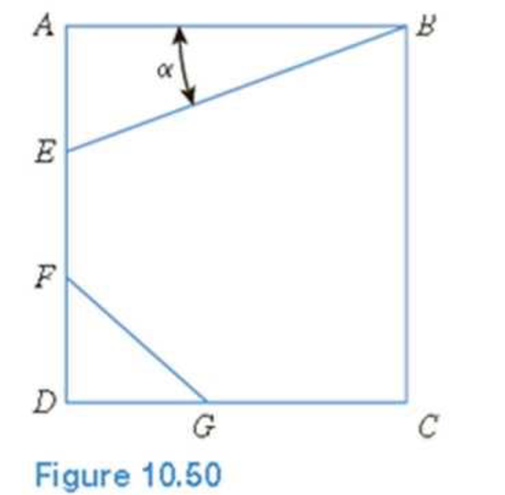
Stress conditions on the two planes are
Plane EB: σEB = 25 kN/m2; τEB = +10 kN/m2
Plane FG: σFG = 10 kN/m2; τFG = –5 kN/m2
(Note: Mohr’s circle sign conventions for stresses are used above)
Given α; = 25°, determine:
- a. The maximum and minimum principal stresses
- b. The angle between the planes EB and FG
- c. The external stresses on planes AB and BC that would cause the above internal stresses on planes EB and FG
Expert Solution & Answer

Trending nowThis is a popular solution!

Students have asked these similar questions
Refer to Figure P6.3. Determine the vertical stress increase Δσ at point A with the values q1 = 90 kN/m, q2 = 325 kN/m, x1 = 4 m, x2 = 2.5 m, and z = 3 m.
3. The following convergence measurements (U) have been made in a 4.6-m-diameter circular vertical shaft in good quality granitic rock mass (Em = 40 GPa, ν = 0.2): θ (deg) U (mm) 0 2.25 45 2.39 90 1.50 135 1.00
a) Derive the equations that relate convergence to in situ stress.
b) The angle θ is measured (clockwise) with respect to the x-axis, which is oriented 30 degrees clockwise from True North. What is the orientation of the maximum principal stress with respect to True North?
Point loads of magnitude 9, 18, and 27 kN act at A, B, and C, respectively(Figure 6.27). Determine the increase in vertical stress at a depth of 3 mbelow point D. Using Westergaard solution. Use μs = 0.4.
Chapter 10 Solutions
Principles of Geotechnical Engineering (MindTap Course List)
Ch. 10 - Prob. 10.1PCh. 10 - Prob. 10.2PCh. 10 - Prob. 10.3PCh. 10 - Prob. 10.4PCh. 10 - Prob. 10.5PCh. 10 - Prob. 10.6PCh. 10 - Point loads of magnitude 125, 250, and 500 kN act...Ch. 10 - Refer to Figure 10.41. Determine the vertical...Ch. 10 - For the same line loads given in Problem 10.8,...Ch. 10 - Refer to Figure 10.41. Given: q2 = 3800 lb/ft, x1...
Ch. 10 - Refer to Figure 10.42. Due to application of line...Ch. 10 - Refer to Figure 10.43. A strip load of q = 1450...Ch. 10 - Repeat Problem 10.12 for q = 700 kN/m2, B = 8 m,...Ch. 10 - Prob. 10.14PCh. 10 - For the embankment shown in Figure 10.45,...Ch. 10 - Refer to Figure 10.46. A flexible circular area of...Ch. 10 - Refer to Figure 10.47. A flexible rectangular area...Ch. 10 - Refer to the flexible loaded rectangular area...Ch. 10 - Prob. 10.19PCh. 10 - Prob. 10.20PCh. 10 - Refer to Figure 10.48. If R = 4 m and hw = height...Ch. 10 - Refer to Figure 10.49. For the linearly increasing...Ch. 10 - EB and FG are two planes inside a soil element...Ch. 10 - A soil element beneath a pave ment experiences...
Knowledge Booster


Learn more about
Need a deep-dive on the concept behind this application? Look no further. Learn more about this topic, civil-engineering and related others by exploring similar questions and additional content below.Similar questions
- Repeat Problem 10.12 for q = 700 kN/m2, B = 8 m, and z = 4 m. In this case, point A is located below the centerline under the strip load. 10.12 Refer to Figure 10.43. A strip load of q = 1450 lb/ft2 is applied over a width with B = 48 ft. Determine the increase in vertical stress at point A located z = 21 ft below the surface. Given x = 28.8 ft. Figure 10.43arrow_forwardGiven H1 = 8.3 m., and H2 = 4.43 m. If the ground water table rises by 2.29 meters, determine the change in effective stress (numerical value only, in kPa) at the bottom of the clay layer. Properties of dry sand: Gs = 2.59, e = 0.61. Properties of clay: Gs = 2.74, e = 0.86. Round off to two decimal places. Answer: 13.95arrow_forwardQ#3. An earth embankment diagram is shown in Figure.1. Determine the vertical stress increase at A due to embankment load.arrow_forward
- 40 Refer to the soil profile shown. Given H1 = 9.89 m., and H2 = 4.4 m. If the ground water table rises by 3.13 meters, determine the change in effective stress (numerical value only, in kPa) at the bottom of the clay layer. Properties of dry sand: Gs = 2.54, e = 0.69. Properties of clay: Gs = 2.77, e = 0.85. Round off to two decimal places.arrow_forward44.) A 5 m-thick clay (Gs = 2.65, water content = 0.28) is overlain by a 4.50m-thick layer of sand (Gs = 2.60, e = 0.70, S = 0.85). The ground water table is located 4.50 m from the ground surface. Compute for the following: 1. At what depth would the vertical effective stress be equal to 120 kPa? 2. What is the vertical effective stress at a depth 9 m below the ground surface? 3. The depth of excavation required to reduce the effective stress at the bottom of the clay layer by 100 kPa. Question 1: A. 1.94 Question 1: B. 3.99 Question 1: C. 6.44 Question 1: D. 8.49 Question 2: A. 168.9 Question 2: B. 44.1 Question 2: C. 120.1 Question 2: D. 124.8 Question 3: A. 1.83 Question 3: B. 7.67 Question 3: C. 3.17 Question 3: D. 6.33arrow_forwardRefer to Figure 10.47. A exible rectangular area is subjected to a uniformly distributed load of q 5 330 kN/m2. Determine the increase in vertical stress, D z, at a depth of z 5 6 m under points A, B, and C .details about me sending through picturesarrow_forward
- For the same line loads given in Problem 10.8, determine the vertical stress increase, z, at a point located 4 m below the line load, q2. Refer to Figure 10.41. Determine the vertical stress increase, z, at point A with the following values: q1 = 110 kN/m, q2 = 440 kN/m, x1 = 6 m, x2 = 3 m, and z = 4 m. Figure 10.41arrow_forwardRefer to Figure 10.46. A flexible circular area of radius 6 m is uniformly loaded. Given: q = 565 kN/m2. Using Newmarks chart, determine the increase in vertical stress, z, at point A. Figure 10.46arrow_forward
arrow_back_ios
arrow_forward_ios
Recommended textbooks for you
 Principles of Geotechnical Engineering (MindTap C...Civil EngineeringISBN:9781305970939Author:Braja M. Das, Khaled SobhanPublisher:Cengage Learning
Principles of Geotechnical Engineering (MindTap C...
Civil Engineering
ISBN:9781305970939
Author:Braja M. Das, Khaled Sobhan
Publisher:Cengage Learning
Stress Distribution in Soils GATE 2019 Civil | Boussinesq, Westergaard Theory; Author: Gradeup- GATE, ESE, PSUs Exam Preparation;https://www.youtube.com/watch?v=6e7yIx2VxI0;License: Standard YouTube License, CC-BY