
Concept explainers
Videos
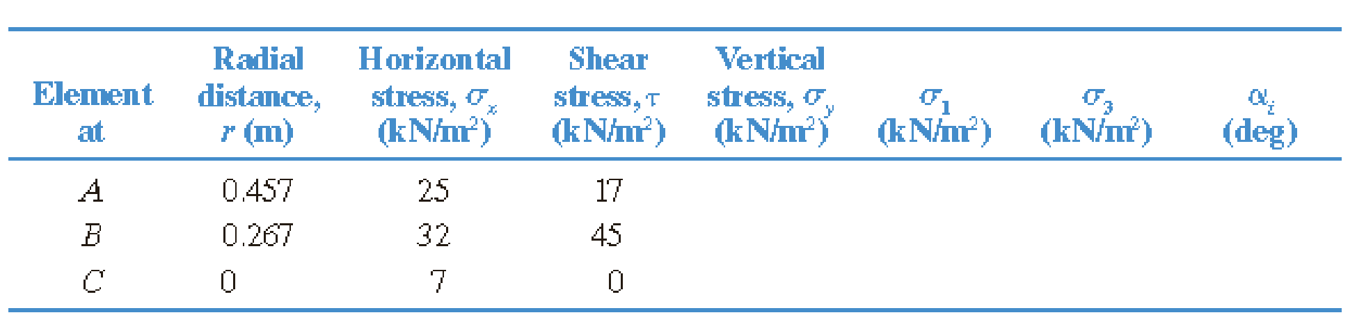
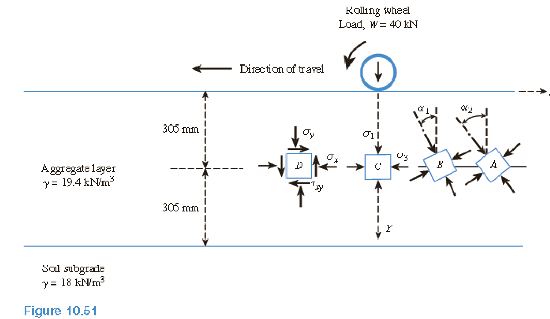
A soil element beneath a pave ment experiences principal stress rotations when the wheel load, W, passes over it and moves away, as shown in Figure 10.51. In this case, the wheel load has passed over points A and B and is now over point C. The general state of stress at these points is similar to the one shown by a stress block at point D. The phenomenon of principal stress rotation influences the permanent deformation behavior of the pavement layers.
Investigate how the magnitude and the orientations of the principal stresses vary with distance from the point of application of the wheel load. Consider the case shown in Figure 10.51. An unpaved aggregate road with a thickness of 610 mm and unit weight of 19.4 kN/m3 is placed over a soil subgrade. A typical single-axle wheel load, W = 40 kN, is applied uniformly over a circular contact area with a radius of R = 150 mm (tire pressure of 565 kN/m2). The horizontal and shear stresses at each point are calculated from a linear elastic finite element analysis for a two-layer pavement and are presented in the following table.
- a. Use Eq. (10.28) to calculate the vertical stress increases at soil elements A, B, and C that are located at radial distances 0.457,0.267, and 0 m, respectively, from the center of the load. Determine the total vertical stress (σy) due to wheel load, the overburden pressure at each point, and enter these values in the table.
- b. Use the pole method to determine the maximum and minimum principal stresses (σ1 and σ3) for elements A, B, and C. Also determine the orientation (αs) of the principal stress with respect to the vertical. Enter these values in the table.
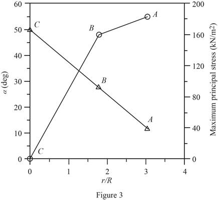
- c. Plot the variations of σ1 and αs, with normalized radial distance, r/R, from the center of loading.
(a)
Calculate the total vertical stress
Explanation of Solution
Given information:
The thickness of unpaved aggregate road
The unit weight of aggregate layer
The radius of the wheel
A typical single-axle wheel load
The tire pressure
The radial distance, horizontal stress, and shear stresses at each point are given in the Table.
Calculation:
Consider the unit weight of water
Calculate the increase in vertical stress
Here,
Calculate the depth to radius ratio
Substitute
For the radial distance
Calculate the ratio
Substitute
Similarly calculate the remaining values and tabulate as in Table 1.
Calculate the value of
Refer Table 10.8 “Variation of
Take the value of
Similarly calculate the remaining values and tabulate as in Table 1.
Calculate the value of
Refer Table 10.9 “Variation of
Take the value of
Similarly calculate the remaining values and tabulate as in Table 1.
Calculate the increase in vertical stress
Substitute
Similarly calculate the increase in vertical stress values and tabulate as in Table 1.
Calculate the overburden pressure at the middle of the
Substitute
Calculate the total vertical pressure at each point using the relation.
For element A.
Substitute
Show the increase in vertical stress for each radial distances as in Table 1.
| El. | Depth, |
Radial distance |
|
| Vertical stress, | |||
| A | 0.305 | 0.457 | 2 | 3 | 0.02221 | 0.00028 | 12.7 | 18.62 |
| B | 0.305 | 0.267 | 2 | 1.78 | 0.05278 | 0.04391 | 54.63 | 60.55 |
| C | 0.305 | 0 | 2 | 0 | 0.10557 | 0.17889 | 160.71 | 166.63 |
Table 1
(b)
Calculate the maximum and minimum principal stresses for elements A, B, and C and the orientation of the principal stress with respect to the vertical using pole method.
Explanation of Solution
Given information:
The thickness of road
The unit weight of aggregate layer
The radius of the wheel
A typical single-axle wheel load
The tire pressure
The radial distance, horizontal stress, and shear stresses at each point are given in the Table.
Calculation:
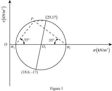
Apply the procedure to construct the Mohr’s circle as shown below.
- Find the center of the circle
- Find the radius
- Sketch the Mohr’s circle once R has been determined.
- Draw a line CP parallel to the plane. Point P is the pole.
- Draw a line PD parallel to the plane AB. The point of intersection with Mohr’s circle is D.
- The coordinates of Q give the stresses on the plane AB.
For element A.
Calculate the center of the Mohr’s circle from the origin
Substitute
Similarly calculate the remaining values and tabulate as in Table 2.
Calculate the radius
Substitute
Similarly calculate the remaining values and tabulate as in Table 2.
Calculate the maximum principal stress
Substitute
Hence, the maximum principal stress
Similarly calculate the remaining values and tabulate as in Table 2.
Calculate the minimum principal stress
Substitute
Hence, the minimum principal stress
Similarly calculate the remaining values and tabulate as in Table 2.
The maximum principal stress acts on the plane inclined at an angle of
The angle
Similarly calculate the remaining values and tabulate as in Table 2.
Show the calculated the maximum and minimum principal stresses of each element as shown in Table 2.
| El. | Vertical stress, | Centre of the circle | Radius of the circle | |||
| A | 18.62 | 21.81 | 17.3 | 39 | 4.5 | 55 |
| B | 60.55 | 46.28 | 47.21 | 93 | 1 | 48 |
| C | 166.63 | 86.82 | 79.82 | 167 | 7 | 0 |
Table 2
Refer to Table 2.
Sketch the Mohr’s circle for the soil element A as shown in Figure 1.
Sketch the Mohr’s circle for the soil element B as shown in Figure 2.
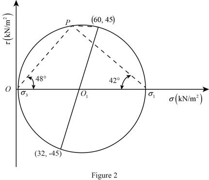
For element B, there is no shear stress. Hence, the horizontal and vertical stresses are principal stresses.
(c)
Plot the variations of
Explanation of Solution
Given information:
The thickness of unpaved aggregate road
The unit weight of aggregate layer
The radius of the wheel
A typical single-axle wheel load
The tire pressure
The radial distance, horizontal stress, and shear stresses at each point are given in the Table.
Calculation:
Refer to Table 2.
Sketch the variations of
Want to see more full solutions like this?
Chapter 10 Solutions
Principles of Geotechnical Engineering (MindTap Course List)


- From the given soil formation of the soil with the following properties is shown in the figure. (see picture below) Compute the total stress at the mid-layer of the clay. (Answer: ) Compute the effective stress at the mid layer of the clay. If a load of 1800 kN is acting on the footing 2m x 2m is placed on the ground, find the stress increase at the mid layer of the clay assuming a stress distribution of 1 horizontal to 2 vertical. *unit weight of dry sand = 14.72 kN/m3*arrow_forward2. The state plane stress in a mass of dense cohesionless sand (c=0) is described by the following stresses: Normal stress on horizontal plane = 100 kPa Normal stress on vertical plane = 50 kPa Shear stress on horizontal and vertical planes = ± 30 kPa Determine by means of the Mohr circle the magnitude and direction of the principal stresses. Is this state of stress safe against failure assuming φ= 30o?arrow_forwardA soil profile consists of a clay layer underlain by a sand layer, as shown in Figure. If a tube is inserted into the bottom sand layer and the water level rises to 1 m above the ground surface, determine the vertical effective stresses and porewater pressures at A, B, and C. What is the value of the porewater pressure at A to cause the vertical effective stress there to be zero?arrow_forward
- A soil element is shown in Figure 10.33. Determine the following:a. Maximum and minimum principal stressesb. Normal and shear stresses on the plane ABarrow_forwardQ#3. An earth embankment diagram is shown in Figure.1. Determine the vertical stress increase at A due to embankment load.arrow_forwardA soil element is shown in the figure below.  Determine the following: (in kPa) a. Maximum and Minimum Principal Stress c. Normal Stress and Shear Stress on plane ABarrow_forward
- According to the elastic theory, the vertical stress induced by a point load of magnitude Q on the surface of a semi-infinite soil mass can be estimated by the expression. A point load Q=1500 kN is applied at the ground surface. Evaluate the stress in the soil caused by the point load at a depth of 2.5m directly below the load in kPa. Evaluate the stress at a depth of 2.5m and a horizontal distance of 3m from the point load.arrow_forwardA soil particle is found to be subjected to a maximum stress of 14.6KN/m2 and a minimum stress of - 4.18KN/m2. Find vertical and shear on the plane of angle of friction is 50o with respect to the major principal stress and also find maximum sheararrow_forwardIn the given soil profile below determine the following: Maximum and minimum Principal stresses. Normal and shear stress on the shear Plane AE.arrow_forward
- The soil profile shown consists of dry sand (4-m thick) which overlies a layer of clay (3-m thick). Ground water table is located at the interface of the sand and clay. a. If the water table rises to the top of the ground surface, what is the change in the effective stress (in kPa) at the bottom of the clay layer? Round off to two decimal places. (ANSWER: 26.336) b. Compute the effective stress at the bottom of the clay layer in kPa. Round off to three decimal places (ANSWER: 97.686) c. How many meters must the ground water table rise to decrease the effective stress by 14 kPa, at the bottom of the clay layer? Round off to two decimal places (ANSWER: 2.13)arrow_forwardA cylindrical sample of saturated clay 4 cm in diameter and 8 cm high was tested in an unconfined compression apparatus. Find the unconfined compression strength, if the specimen failed at an axial load of 360 N, when the axial deformation was 8 mm. Find the cohesion in kPa if the angle made by the failure plane with the horizontal plane was recorded as 50°. Include free body diagram. a.312 b.106 c.258 d.210arrow_forwardA sample of soil (0.1 m X 0.1 m) is subjected to the forces shown in Figure below. Determine (a) σ1, σ3, and α;(b) the maximum shear stress; and (c) the stresses on a plane oriented at 30° counterclockwise from the major principal stress plane.arrow_forward
 Principles of Geotechnical Engineering (MindTap C...Civil EngineeringISBN:9781305970939Author:Braja M. Das, Khaled SobhanPublisher:Cengage Learning