
Principles of Geotechnical Engineering (MindTap Course List)
9th Edition
ISBN: 9781305970939
Author: Braja M. Das, Khaled Sobhan
Publisher: Cengage Learning
expand_more
expand_more
format_list_bulleted
Concept explainers
Videos
Textbook Question
Chapter 10, Problem 10.18P
Refer to the flexible loaded rectangular area shown in Figure 10.47. Using Eq. (10.36), determine the vertical stress increase below the center of the loaded area at depths z = 3, 6, 9, 12, and 15 m.
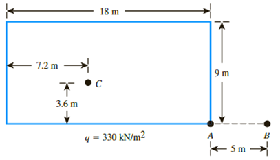
Figure 10.47
Expert Solution & Answer

Trending nowThis is a popular solution!

Students have asked these similar questions
Consider a circularly loaded flexible area on the ground surface. Given: radius of the circular area, R = 3 m; uniformly distributed load, q = 250 kN/m 2.Calculate the vertical stress increase Δσ at a point located 5 m (z) below the ground surface (immediately below the center of the circular area).
Consider a circularly loaded flexible area acting on the ground surface. The radius of the circular area is 20 ft and the uniformly distributed load is q = 1,000 lb/ft2. Calculate the vertical stress increase, Δσz, at a depth of 10 ft for a radius of 0 ft (immediately below the center of the circular area) and 20 ft (immediately below the edge of the circular area).
Calculate the vertical stress increases occurring at points A1 and A2 under a long earth fill shown in the figure. Unit weight of the earth ɣ=17.5kN/m3
Chapter 10 Solutions
Principles of Geotechnical Engineering (MindTap Course List)
Ch. 10 - Prob. 10.1PCh. 10 - Prob. 10.2PCh. 10 - Prob. 10.3PCh. 10 - Prob. 10.4PCh. 10 - Prob. 10.5PCh. 10 - Prob. 10.6PCh. 10 - Point loads of magnitude 125, 250, and 500 kN act...Ch. 10 - Refer to Figure 10.41. Determine the vertical...Ch. 10 - For the same line loads given in Problem 10.8,...Ch. 10 - Refer to Figure 10.41. Given: q2 = 3800 lb/ft, x1...
Ch. 10 - Refer to Figure 10.42. Due to application of line...Ch. 10 - Refer to Figure 10.43. A strip load of q = 1450...Ch. 10 - Repeat Problem 10.12 for q = 700 kN/m2, B = 8 m,...Ch. 10 - Prob. 10.14PCh. 10 - For the embankment shown in Figure 10.45,...Ch. 10 - Refer to Figure 10.46. A flexible circular area of...Ch. 10 - Refer to Figure 10.47. A flexible rectangular area...Ch. 10 - Refer to the flexible loaded rectangular area...Ch. 10 - Prob. 10.19PCh. 10 - Prob. 10.20PCh. 10 - Refer to Figure 10.48. If R = 4 m and hw = height...Ch. 10 - Refer to Figure 10.49. For the linearly increasing...Ch. 10 - EB and FG are two planes inside a soil element...Ch. 10 - A soil element beneath a pave ment experiences...
Knowledge Booster


Learn more about
Need a deep-dive on the concept behind this application? Look no further. Learn more about this topic, civil-engineering and related others by exploring similar questions and additional content below.Similar questions
- For the same line loads given in Problem 10.8, determine the vertical stress increase, z, at a point located 4 m below the line load, q2. Refer to Figure 10.41. Determine the vertical stress increase, z, at point A with the following values: q1 = 110 kN/m, q2 = 440 kN/m, x1 = 6 m, x2 = 3 m, and z = 4 m. Figure 10.41arrow_forwardRepeat Problem 10.12 for q = 700 kN/m2, B = 8 m, and z = 4 m. In this case, point A is located below the centerline under the strip load. 10.12 Refer to Figure 10.43. A strip load of q = 1450 lb/ft2 is applied over a width with B = 48 ft. Determine the increase in vertical stress at point A located z = 21 ft below the surface. Given x = 28.8 ft. Figure 10.43arrow_forwardA point load of 500 kN is applied at the ground level. Plot the lateral variation of the vertical stress increase at depths of 2 m, 3 m, and 4 m below the ground level.arrow_forward
- A 10 ft diameter flexible loaded area is subjected to a uniform pressure of 1200 lb/ft2. Plot the variation of the vertical stress increase beneath the center with depth z = 0 to 20 ft. In the same plot, show the variation beneath the edge of the loaded area.arrow_forwardRefer to Figure 8.24. Determine the vertical stress increase, , at point A with the following values: q1 = 100 kN/m x1 = 3 m z = 2 m q2 = 200 kN/m x2 = 2 m FIG. 8.24 Stress at a point due to two line loadsarrow_forwardRefer to Figure 10.48. If R = 4 m and hw = height of water = 5 m, determine the vertical stress increases 2 m below the loaded area at radial distances where r = 0, 2, 4, 6, and 8 m. Circular contact area of radius R on the ground surface Figure 10.48arrow_forward
- Refer to Figure 8.13. The magnitude of the line load q is 45 kN/m. Calculate and plot the variation of the vertical stress increase, between the limits of x = 10 m and x = +10 m, given z = 4 m. FIG. 8.13 Line load over the surface of a semiinfinite soil massarrow_forwardUse Eq. (6.14) to determine the stress increase () at z = 10 ft below the center of the area described in Problem 6.5. 6.5 Refer to Figure 6.6, which shows a flexible rectangular area. Given: B1 = 4 ft, B2 = 6 ft, L1, = 8 ft, and L2 = 10 ft. If the area is subjected to a uniform load of 3000 lb/ft2, determine the stress increase at a depth of 10 ft located immediately below point O. Figure 6.6 Stress below any point of a loaded flexible rectangular areaarrow_forwardRefer to Figure 8.27. The flexible area is uniformly loaded. Given: q = 300 kN/m2. Determine the vertical stress increase at point A located at depth 3 m below point A (shown in the plan). FIG. 8.27arrow_forward
- Refer to Figure 10.46. A flexible circular area of radius 6 m is uniformly loaded. Given: q = 565 kN/m2. Using Newmarks chart, determine the increase in vertical stress, z, at point A. Figure 10.46arrow_forwardRedo Problem 6.12 using Figure 6.15. 6.12 Refer to Problem 6.1. Using Eqs. (6.3) and (6.29), estimate the average stress increase (av) below the center of the loaded area between depths of 3 m and 6 m. 6.1 A flexible circular area is subjected to a uniformly distributed load of 150 kN/m2 (Figure 6.2). The diameter of the load area is 2 m. Determine the stress increase in a soil mass at points located 3 m below the loaded area at r = 0, 0.4 m, 0.8 m, and 1 m. Use Boussinesqs solution. Figure 6.2 Increase in pressure under a uniformly loaded flexible circular areaarrow_forwardA borehole at a site reveals the soil profile shown below. Calculate the effective stress (σ’) in kN/m2 at the bottom of the sand layer. 2 m Water 3 m Clay, Void ratio = 0.8, Gs = 2.6 15 m Sand, Void ratio = 0.6, Gs = 2.7arrow_forward
arrow_back_ios
SEE MORE QUESTIONS
arrow_forward_ios
Recommended textbooks for you
 Principles of Geotechnical Engineering (MindTap C...Civil EngineeringISBN:9781305970939Author:Braja M. Das, Khaled SobhanPublisher:Cengage Learning
 Fundamentals of Geotechnical Engineering (MindTap...Civil EngineeringISBN:9781305635180Author:Braja M. Das, Nagaratnam SivakuganPublisher:Cengage Learning
 Principles of Foundation Engineering (MindTap Cou...Civil EngineeringISBN:9781337705028Author:Braja M. Das, Nagaratnam SivakuganPublisher:Cengage Learning
 Principles of Foundation Engineering (MindTap Cou...Civil EngineeringISBN:9781305081550Author:Braja M. DasPublisher:Cengage Learning
Principles of Geotechnical Engineering (MindTap C...
Civil Engineering
ISBN:9781305970939
Author:Braja M. Das, Khaled Sobhan
Publisher:Cengage Learning
Fundamentals of Geotechnical Engineering (MindTap...
Civil Engineering
ISBN:9781305635180
Author:Braja M. Das, Nagaratnam Sivakugan
Publisher:Cengage Learning
Principles of Foundation Engineering (MindTap Cou...
Civil Engineering
ISBN:9781337705028
Author:Braja M. Das, Nagaratnam Sivakugan
Publisher:Cengage Learning
Principles of Foundation Engineering (MindTap Cou...
Civil Engineering
ISBN:9781305081550
Author:Braja M. Das
Publisher:Cengage Learning
Stress Distribution in Soils GATE 2019 Civil | Boussinesq, Westergaard Theory; Author: Gradeup- GATE, ESE, PSUs Exam Preparation;https://www.youtube.com/watch?v=6e7yIx2VxI0;License: Standard YouTube License, CC-BY