
Applied Statics and Strength of Materials (6th Edition)
6th Edition
ISBN: 9780133840728
Author: Limbrunner
Publisher: PEARSON
expand_more
expand_more
format_list_bulleted
Videos
Textbook Question
Chapter 10, Problem 10.26SP
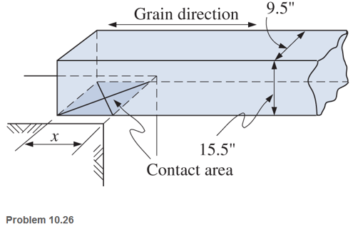
Calculate the end bearing length required for a 10-in.-by-16-in. timber beam (dressed) that is supported on a reinforced concrete wall as shown. The beam reaction is 15.000 lb and the allowable compressive stress perpendicular to the grain for the timber member is 300 psi.
Expert Solution & Answer
Want to see the full answer?
Check out a sample textbook solution
Students have asked these similar questions
Calculate the end bearing length (in.) required for a 10-in.-by-16-in. timber beam (dressed) that is supported on a reinforced concrete wall as shown. The beam reaction is 18,000 lb and the allowable compressive stress perpendicular to the grain for the timer member is 400 psi. (Unit: in.)
a rectangular beam with a span of 20ft is simply supported at both ends. The maximum flexural stress for the beam is 1200 psi and the dimensions of its cross-section are: b=4 in and h=10 in. If the beam is to be loaded at mid-span with a concentrated load of 2000lbs, will the beam collapse?
A 4-m long simply supported beam has a section modulus of 1408 x 10³ mm³. The allowable stress in the beam is not to exceed 100MPa. The maximum distributed load that the beam can carry is most nearly,
Chapter 10 Solutions
Applied Statics and Strength of Materials (6th Edition)
Ch. 10 - A 916 - in. - diameter steel rod is tested in...Ch. 10 - A concrete cylinder 150 mm in diameter was tested...Ch. 10 - Prob. 10.3PCh. 10 - The data from the tension test of a steel specimen...Ch. 10 - An 18-in.-long titanium alloy rod is subjected to...Ch. 10 - ASTM A36 steel rods are used to support a balcony....Ch. 10 - A 450-mm-long AISI 1020 steel rod is subjected to...Ch. 10 - A tension member in a roof truss is composed of...Ch. 10 - A short, solid, compression member of circular...Ch. 10 - A main cable in a large bridge is designed for a...
Ch. 10 - Test results of a steel specimen indicated an...Ch. 10 - A concrete canoe in storage is supported by two...Ch. 10 - A load is applied to a rigid bar that is...Ch. 10 - Prob. 10.14CPCh. 10 - Write a program that will allow a user to input...Ch. 10 - A 12 - in. - diaiíct.cr structural nickel steel...Ch. 10 - Compute the modulus of elasticity of a copper...Ch. 10 - A concrete cylinder 6 in. in diameter was tested...Ch. 10 - An aluminum bar 2 in. by 12 - in. in cross section...Ch. 10 - During a tensile test of a steel specimen, the...Ch. 10 - A 12.5-mm-diameter steel rod was subjected to a...Ch. 10 - Prob. 10.22SPCh. 10 - A standard steel specimen having a diameter of...Ch. 10 - 10.24 A tension member in a structure is composed...Ch. 10 - A pair of wire cutters is designed to operate...Ch. 10 - Calculate the end bearing length required for a...Ch. 10 - Design a 3-m-long rod subjected to a tensile load...Ch. 10 - The collar bearing shown is subjected to a...Ch. 10 - A 10-ft-long steel member is subjected to a...Ch. 10 - Two steel bars A and B support a load P, as shown....Ch. 10 - Prob. 10.31SP
Knowledge Booster


Learn more about
Need a deep-dive on the concept behind this application? Look no further. Learn more about this topic, mechanical-engineering and related others by exploring similar questions and additional content below.Similar questions
- A cast iron beam is of T-section as shown in Fig. The beam is simply supported on a span of 6 m. The beam carries a uniformly distributed load of 2 kN/m length on the entire span. Determine the maximum tensile and maximum compressive stresses.arrow_forwardA beam of rectangular cross-section is 64 mm broad, 100 mm deep, and 1.6 m long. It is simply supported at each end and carries a concentrated load of 10 kN at its mid-length. Neglecting the weight of the beam, find the maximum stress in the material.arrow_forwardA brass strip, 50 mm x 12 mm in section, is riveted to a steel strip, Figure (22) 65 mm x 10 mm in section, to form a compound beam of total depth 22 mm, the brass strip being on top and the beam section being symmetrical about the vertical axis. The beam is simply supported on a span of 1.3 m and carries a load of 2 kN at mid-span. (a) Determine the maximum stresses in each of the materials owing to bending. (b) Make a diagram showing the distribution of bending stress over the depth of the beam. Take E for steel = 200 GN/m² and E for brass = 100 GN/m². Ans.( 0) = 130 MN/m²; 0, = 162.9 MN/m²]arrow_forward
- Since the allowable normal stress of AC beam loaded with uniformly distributed load is 100MPa in tensile, 120MPa in compression and 50MPa in shear stress, check whether the beam is safe.arrow_forwardA cantilever beam, 80 mm wide by 240 mm high and 8 m long, carries a load that varies uniformly from zero at the free end to 1100 N/m at the wall. Compute the magnitude of the maximum flexural stress. Answer must be in MPa.arrow_forwardA 2500 lbs point load is placed at 4 inches from support A. The beam is simply supported with a span of 16 inches. Determine the maximum flexural stress of the beam.arrow_forward
- Select a wide-flange beam to support the 15-kip load as shown in Fig.. The allowable normal stress for the steel used is 24 ksi.arrow_forwardA steel beam of I cross-section is simply supported on a span of 4m. Find the safe uniformly distributed load the beam can carry if the tensile stress is not to exceed 26 N/mm2. Also find the maximum compressive stress.arrow_forwardWrite down the stress types acting on each bar in the supported beam system above.arrow_forward
- A flat steel bar, 26 mm wide by 5 mm thick and 1.6 m long, is bent by couples applied at the ends so that the midpoint deflection is 24 mm. Compute the maximum stress in the bar. Use E = 220 GPa. Answer must be in MPa.arrow_forwardFigure 6 shows a beam of length 8 m, simply supported at each end, and loadedwith a point load of 60 kN and a uniformly distributed load of 30 kN/m over 6m of thebeam.arrow_forwardThe cross section of a reinforced concrete beam is shown below. It has a modular ratio of 15. If the allowable compressive stress in the concrete is 6 MPa and the allowable tensile stress in the steel is 120 MPa, determine diameter of the three reinforcing steel rods to make the beam an economic section.arrow_forward
arrow_back_ios
arrow_forward_ios
Recommended textbooks for you
 Mechanics of Materials (MindTap Course List)Mechanical EngineeringISBN:9781337093347Author:Barry J. Goodno, James M. GerePublisher:Cengage Learning
Mechanics of Materials (MindTap Course List)
Mechanical Engineering
ISBN:9781337093347
Author:Barry J. Goodno, James M. Gere
Publisher:Cengage Learning
Mechanics of Materials Lecture: Beam Design; Author: UWMC Engineering;https://www.youtube.com/watch?v=-wVs5pvQPm4;License: Standard Youtube License