Videos
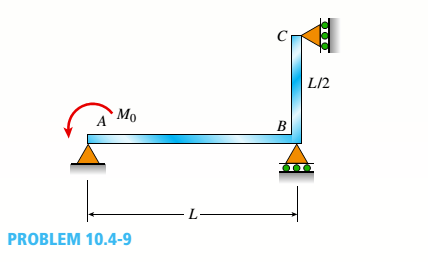
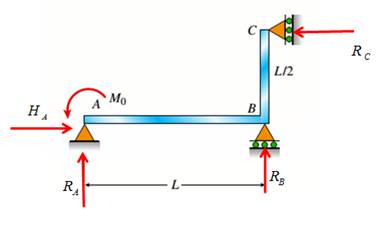
The continuous frame ABC has a pin support at A, roller supports at B and C and a rigid corner connection at B (see figure). Members AB and BC each have flexural rigidity EI. A moment Müacts counterclockwise at A. Note: Disregard axial deformations in member AB and consider only the effects of bending.
- Find all reactions of the frame.
Find the required new length of member AB in terms of L, so that
(a)
All the reactions of the frame.
Answer to Problem 10.4.9P
The reactions are :
Explanation of Solution
Given Information:
The following figure is given with all relevant information,

Calculation:
Consider the following free body diagram,
Take equilibrium of horizontal forces as,
Take equilibrium of vertical forces as,
Take equilibrium of moments about B as,
The bending moment at distance x from A along AB in part AB is given by,
Use second order deflection differential equation,
Integrate above equation to get rotation as,
Integrate above equation to get rotation as,
The bending moment at distance x from B along BC in part BC is given by,
Use second order deflection differential equation,
Integrate above equation to get rotation as,
Integrate above equation to get rotation as,
The constraint equations are,
Solve equations (1-8) to get integration constants and reactions.
So the reactions are
Conclusion:
Therefore, the reactions are:
(b)
Rotations at joints A, B, and C.
Answer to Problem 10.4.9P
Rotations at joints A, B, and C are
Explanation of Solution
Given Information:
The following figure is given with all relevant information,

Calculation:
Consider the following free body diagram,

Take equilibrium of horizontal forces as,
Take equilibrium of vertical forces as,
Take equilibrium of moments about B as,
The bending moment at distance x from A along AB in part AB is given by,
Use second order deflection differential equation,
Integrate above equation to get rotation as,
Integrate above equation to get rotation as,
The bending moment at distance x from B along BC in part BC is given by,
Use second order deflection differential equation,
Integrate above equation to get rotation as,
Integrate above equation to get rotation as,
The constraint equations are,
Solve equations (1-8) to get integration constants and reactions.
So the reactions are
Substitute the integration constants and reactions in expressions of rotations to get,
Conclusion:
Therefore, rotations at joints A, B, and C are
(c)
Length of AB.
Answer to Problem 10.4.9P
Length of AB is
Explanation of Solution
Given Information:
The following figure is given with all relevant information,
Also
Calculation:
Consider the following free body diagram,

Take equilibrium of horizontal forces as,
Take equilibrium of vertical forces as,
Take equilibrium of moments about B as,
The bending moment at distance x from A along AB in part AB is given by,
Use second order deflection differential equation,
Integrate above equation to get rotation as,
Integrate above equation to get rotation as,
The bending moment at distance x from B along BC in part BC is given by,
Use second order deflection differential equation,
Integrate above equation to get rotation as,
Integrate above equation to get rotation as,
The constraint equations are,
Solve equations (1-8) to get integration constants and reactions.
So the reactions are
Substitute the integration constants and reactions in expressions of rotations to get,
Solve above equation to get
Conclusion:
Therefore, length of AB is
Want to see more full solutions like this?
Chapter 10 Solutions
Mechanics of Materials - Text Only (Looseleaf)


- Beam A BCD has a sliding support at A, roller supports at C and A and a pin connection at B (see figure). Assume that the beam has a rectangular cross section (b = 4 in., h = 12 in.). Uniform load q acts on ABC and a concentrated moment is applied at D. Let load variable q = 1750 lb/ft, and assume that dimension variable L = 4 ft. First, use statics to confirm the reaction moment at A and the reaction forces at Cand A as given in the figure. Then find the ratio of the magnitudes of the principal stresses (crj/os) just left of support Cat a distance d = 8 in. up from the bottom,arrow_forwardBeam A BCD has a sliding support at A, roller supports at C and A and a pin connection at B (see figure). Assume that the beam has a rectangular cross section (b = 4 in., h = 12 in.). Uniform load q acts on ABC and a concentrated moment is applied at D. Let load variable q = 1750 lb/ft, and assume that dimension variable L = 4 ft. First, use statics to confirm the reaction moment at A and the reaction forces at C and A as given in the figure. Then find the ratio of the magnitudes of the principal stresses (crj/os) just left of support Cat a distance d = 8 in. up from the bottom, The pedal and crank are in a horizontal plane and points A and B are located on the top of the crank. The load P = 160 lb acts in the vertical direction and the distances (in the horizontal plane) between the line of action of the load and points A and B are b\ = 5.0 in., h-, = 2.5 in., and/>3 = 1.0 in. Assume that the crank has a solid circular cross section with diameter d = 0.6 inarrow_forwardFind support reactions at A and D and then calculate the axial force N. shear force 1 and bending moment 11 at mid-span of column BD. Let L = 4 m, q0 = 160N/m, P = 200N, and M0= 380 N .m.arrow_forward
- The continuous frame ABC has a pinned support at A, a sliding support at C, and a rigid corner connection at B (see figure). Members AB and BC each have length L and flexural rigidity EI. A horizontal force P acts at mid-height of member AB. Find all reactions of the frame. What is the largest bending moment Mmaxin the frame? Note: Disregard axial deformations in members AB and BC and consider only the effects of bending.arrow_forwardSolve the preceding problem for a cantilever beam with data as b = 4 in., h = 9 in., L = 10 ft, P = 325 lb, and x = 45°.arrow_forwardThe continuous frame ABC has a pin support at /l, roller supports at B and C, and a rigid corner connection at B (see figure). Members AB and BC each have flexural rigidity EI. A moment M0acts counterclockwise at B, Note: Disregard axial deformations in member AB and consider only the effects of bending. Find all reactions of the frame. Find joint rotations B at A, B, and C. Find the required new length of member BC in terms of L., so that B in part (b) is doubled in size.arrow_forward
- Frame ABCD carries two concentrated loads (2P at T and P at ZX see figure) and also a linearly varying distributed load on AB, Find expressions for shear force Fand moment A/at x = L/3 of beam AB in terms of peak load intensity q0, force P, and beam length variable L. Let q0= P/L.arrow_forwardSolve the preceding problem using a W 310 x 129 section, L = 1.8 m, P = 9.5 kN, and or x= 60°. See Table F-l(b) of Appendix F For the dimensions and properties of the beam.arrow_forwardA compound beam (see figure) has an shear release just to the left of C and a moment release just to the right of C. A plot of the moment diagram is provided below the beam for applied load P at B and triangular distributed loads v(x) on segments Z/C and CD. First, solve for reactions using statics; then plot axial force (A) and shear force (K) diagrams. Confirm that the moment diagram is that shown below. Label all critical N, V, and M values and also the distance to points where N, V, and/or M are zero.arrow_forward
- A cantilever beam of W 12 × 14 section and length L = 9 ft supports a slightly inclined load P = 500 lb at the free end (see figure). Plot a graph of the stress o 4at point A as a function of the angle of inclination or Plot a graph of the angle L/3, which locates the neutral axis ma as a function of the angle a. (When plotting the graphs, let a vary from 0 to 10º) See Table F-1(a) of Appendix F for the dimensions and properties of the beam.arrow_forwardFind support reactions at A and D and then calculate the axial force N, shear force V, and bending moment M at mid-span of AB. Let L = 14 ft, q0 = 12 lb/ft, P = 50 lb. and = 300 lb-ft.arrow_forwardA foot bridge on a hiking trail is constructed using two timber logs each having a diameter d = 0.5 m (see figure a). The bridge is simply supported and has a length L = 4 m. The top of each log is trimmed to form the walking surface (see Fig, b)LA simplified model of the bridge is shown in Fig. g. Each log must carry its own weight w = 1.2 kN/m and the weight (P = 850 N) of a person at mid-span, (see Fig. b). Determine the maximum tensile and compressive stresses in the beam (Fig, b) due to bending. If load h is unchanged, find the maximum permissible value of load ... if the allowable normal stress in tension and compression is 2.5 M Pa.arrow_forward
 Mechanics of Materials (MindTap Course List)Mechanical EngineeringISBN:9781337093347Author:Barry J. Goodno, James M. GerePublisher:Cengage Learning