
Fox And Mcdonald's Introduction To Fluid Mechanics
9th Edition
ISBN: 9781118921876
Author: Pritchard, Philip J.; Leylegian, John C.; Bhaskaran, Rajesh
Publisher: WILEY
expand_more
expand_more
format_list_bulleted
Concept explainers
Videos
Textbook Question
Chapter 10, Problem 71P
The absolute velocities and directions of the jets entering and leaving the blade system are as shown. Calculate the power transferred from the jet to the blade system and the blade angles required.
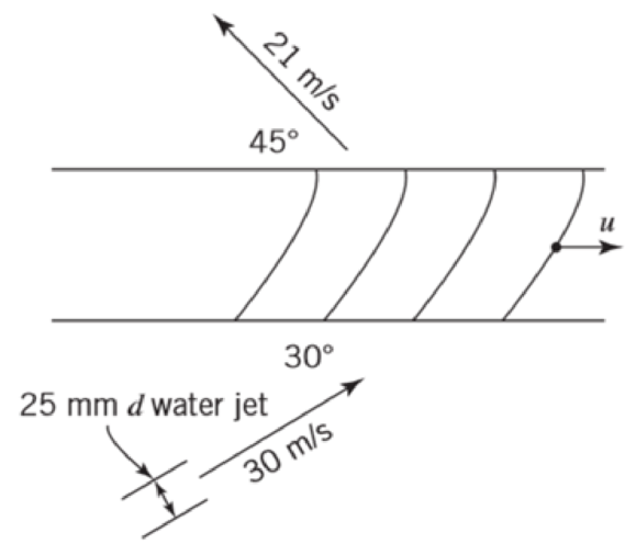
P10.71
Expert Solution & Answer
Want to see the full answer?
Check out a sample textbook solution
Students have asked these similar questions
20. A centrifugal pump has an impeller 45 cms in diameter
running at 450 rpm. - The discharge at inlet is entirely radial. The
velocity of flow at outlet is 12. m/sec. The vanes are curved back-
wards at outlet at 30° to the wheel tangent. If the discharge of the
is 0'15 cumec calculate the impeller horse power and the
(18'42 hp ; 29 31 kgm)
pump
torque on the shaft.
The mean radius of an axial flow reaction turbine is 2.6 ft. and the axial velocityis 25 ft./s. The wicket gates are turned at an angle such that relative velocity at theinlet flow makes an angle of -45° with the blade velocity. The wheel and hub radiiare 3.6 ft. and 1.6 ft., respectively. The turbine rotates at 240 rpm. If water leaves theblade in a purely axial direction, calculate H and all relevant angles.Ans: H=81.87 ft.; α1=31.8°; β2=20.93°
د امتحان يومي.docx
120
Q/ calculate the force excreted on the blade by the jet if the angle
deflection 120 and the
Velocity of jet 30m/s and flow rate 10.
Chapter 10 Solutions
Fox And Mcdonald's Introduction To Fluid Mechanics
Ch. 10 - The geometry of a centrifugal water pump is r1 =...Ch. 10 - Find the resulting -groups when (a) D, , and Q or...Ch. 10 - Consider the centrifugal pump impeller dimensions...Ch. 10 - Dimensions of a centrifugal pump impeller areCh. 10 - Dimensions of a centrifugal pump impeller areCh. 10 - The blade is one of a series. Calculate the force...Ch. 10 - This blade is one of a series. What force is...Ch. 10 - A centrifugal water pump, with 15-cm-diameter...Ch. 10 - A centrifugal water pump designed to operate at...Ch. 10 - A series of blades, such as in Example 10.13,...
Ch. 10 - In passing through this blade system, the absolute...Ch. 10 - A centrifugal pump runs at 1750 rpm while pumping...Ch. 10 - A centrifugal water pump designed to operate at...Ch. 10 - Kerosene is pumped by a centrifugal pump. When the...Ch. 10 - In the water pump of Problem 10.8, the pump casing...Ch. 10 - Use data from Appendix C to choose points from the...Ch. 10 - Data from tests of a water suction pump operated...Ch. 10 - A centrifugal pump impeller having r1 = 50 mm, r2...Ch. 10 - A centrifugal pump impeller having dimensions and...Ch. 10 - An axial-flow fan operates in sea-level air at...Ch. 10 - Data measured during tests of a centrifugal pump...Ch. 10 - A small centrifugal pump, when tested at N = 2875...Ch. 10 - If the impeller of Problem 10.20 rotates between...Ch. 10 - At the outlet of a pump impeller of diameter 0.6 m...Ch. 10 - Typical performance curves for a centrifugal pump,...Ch. 10 - A pump with D = 500 mm delivers Q = 0.725 m3/s of...Ch. 10 - At its best efficiency point ( = 0.87), a...Ch. 10 - Using the performance curves in Appendix C, select...Ch. 10 - A pumping system must be specified for a lift...Ch. 10 - A centrifugal water pump operates at 1750 rpm; the...Ch. 10 - A set of eight 30-kW motor-pump units is used to...Ch. 10 - A blower has a rotor with 12-in. outside diameter...Ch. 10 - A centrifugal water pump has an impeller with an...Ch. 10 - Appendix C contains area bound curves for pump...Ch. 10 - Use data from Appendix C to verify the similarity...Ch. 10 - A centrifugal water pump has an impeller with...Ch. 10 - Catalog data for a centrifugal water pump at...Ch. 10 - A 1/3 scale model of a centrifugal water pump...Ch. 10 - Sometimes the variation of water viscosity with...Ch. 10 - A large deep fryer at a snack-food plant contains...Ch. 10 - Data from tests of a pump, with a...Ch. 10 - A four-stage boiler feed pump has suction and...Ch. 10 - A centrifugal pump operating at N = 2265 rpm lifts...Ch. 10 - A centrifugal pump is installed in a piping system...Ch. 10 - Part of the water supply for the South Rim of...Ch. 10 - Consider the flow system shown in Problem 8.94....Ch. 10 - Afire nozzle is supplied through 300 ft of...Ch. 10 - Performance data for a centrifugal fan of 3-ft...Ch. 10 - The performance data of Problem 10.57 are for a...Ch. 10 - Experimental test data for an aircraft engine fuel...Ch. 10 - Preliminary calculations for a hydroelectric power...Ch. 10 - Conditions at the inlet to the nozzle of a Pelton...Ch. 10 - A Francis turbine is to operate under a head of 46...Ch. 10 - A Kaplan (propeller with variable-pitch blades)...Ch. 10 - Francis turbine Units 19, 20, and 21, installed at...Ch. 10 - Measured data for performance of the reaction...Ch. 10 - For a flow rate of 12 L/s and turbine speed of 65...Ch. 10 - The velocity of the water jet driving this impulse...Ch. 10 - An impulse turbine is to develop 15 MW from a...Ch. 10 - An impulse turbine under a net head of 33 ft was...Ch. 10 - The absolute velocities and directions of the jets...Ch. 10 - A fanboat in the Florida Everglades is powered by...Ch. 10 - A jet-propelled aircraft traveling at 225 m/s...Ch. 10 - When an air jet of 1-in.-diameter strikes a series...Ch. 10 - The volume flow rate through the propeller of an...Ch. 10 - A typical American multi blade farm windmill has D...Ch. 10 - An airplane flies at 200 km/h through still air of...Ch. 10 - This ducted propeller unit drives a ship through...Ch. 10 - A model of an American multi blade farm windmill...Ch. 10 - A large Darrieus vertical axis wind turbine was...Ch. 10 - Show that this ducted propeller system when moving...Ch. 10 - This ducted propeller unit (now operating as a...Ch. 10 - What is the maximum power that can be expected...Ch. 10 - If an ideal windmill is operating at best...Ch. 10 - A prototype air compressor with a compression...Ch. 10 - Prob. 89PCh. 10 - We have seen many examples in Chapter 7 of...
Additional Engineering Textbook Solutions
Find more solutions based on key concepts
Make the following volume and mass flow rate calculations in SI units. (a) Water flowing at an average velocity...
Heating Ventilating and Air Conditioning: Analysis and Design
The special-purpose milling cutter is subjected to the force of 1200 N and a couple of 240Nm as shown. Determin...
Engineering Mechanics: Statics
1.1 What is the difference between an atom and a molecule? A molecule and a crystal?
Manufacturing Engineering & Technology
Rods AC and BC are used to suspend the 200-kg mass. If each rod is made of a material for which the average nor...
Mechanics of Materials (10th Edition)
12. When a fluid flows around an object, it creates a force, called the drag force, that pulls on the object. T...
Thinking Like an Engineer: An Active Learning Approach (4th Edition)
Determine the reactions at D. Prob. F6-20
Engineering Mechanics: Statics
Knowledge Booster


Learn more about
Need a deep-dive on the concept behind this application? Look no further. Learn more about this topic, mechanical-engineering and related others by exploring similar questions and additional content below.Similar questions
- Determine the size of the diesel engine to be used for a 4 inches X 4 inches centrifugal pump. Pump discharge is 200gpm. Total head is 24 ft. Pump efficiency is 55%. V-belt efficiency is 95%. And air-cooled diesel engine delivery rating is 70%. 22. 1.6 hp 3.3 hp b. 2.4 hp 4.7 hp| a. b. d. A 4-m combine traveling at 5 kph can empty its 1.5-ton grain tank in 2 minutes. When unloading on-the-go, it has an 86% field efficiency. Field yield is 3.5 tons/ha. What would be the field efficiency if the combine stopped to load? 23. 70% b. 75% a. C. 80% d. 85% A 4-wheel tractor with 3X14 inches moldboard plow is to operate on clay loam soil (specific draft = 0.56 kg/cm?) at a depth of 25.4 cm. The maximum draft and percent increase in draft due to speed are: 24. Gear Setting Speed (kph) Increase in draft due to speed (%) Max. Draft (kg) 4,000 3,100 2,200 1,300 1L 3.2 14 2L 3L 4.8 28 6.4 42 4L 8.0 56 Determine the tractor horsepower required to perform the operation. 55 hp 65 hp 60 hp 70 hp a. b.…arrow_forward18. A centrifugal pump has to work against a head of 25 metres at a speed of 850 rpm. The flow component of the velocity at outlet is 2'5 metreajeccond. The outlet vane angle is 40°. If the discharge of the pump is 0 25 cumeo find (i) The diameter of the impeller and (ii) The width of the impeller at outlet. Neglect losses. (0:387 m; 0'082 m)arrow_forwardInclude a free body diagram. pump draws water from a sump through a vertical 6′′ pipe. The pump has a horizontal discharge pipe 4′′ in diameter that is 10.6 ft above the water level in the sump. While pumping 1.25 cfs, gages near the pump at entrance and discharge read —4.6 psi and +25.6 psi, respectively. The discharge gage is 3.0 ft above the suction gage. Compute the horsepower output of the pump and the head lost in the 6′′ suction pipe. (ANSWER: 10.7 Hp, 2.4 ft)arrow_forward
- A. A water jet of diameter 180 mm impinges on the buckets of a Pelton turbine having overall efficiency of 85% while operating under a net head of 500 m and at speed of 420 rpm. Find the specific speed of the turbine. Take coefficient of velocity of the jet as 0.98 and speed ratio as 0.46. B. The pitch circle diameter of a Pelton wheel is 0.9 m. A jet of water of diameter 80 mm gets deflected by an angle of 170° when it impinges on the buckets. The bucket friction coefficient and coefficient of velocity of jet can be taken as 0.93 and 0.97 respectively. If the net head available on the wheel is 500 m and speed ratio is 0.45, calculate (a) the power transferred to to the wheel by the jet, (b) hydraulic efficiency, and (c) specific speed of the turbine. Take mechanical efficiency of wheel as 0.9.arrow_forwardThe hub diameter of a Kaplan turbine is 0.85 m and outer diameter of the blades is 2.5 m. The turbine develops 20 MW power under a head of 35 m at a rotational speed of 420 rpm. The hydraulic efficiency of the turbine is 88% and overall efficiency is 85%. Calculate the inlet blade angle at the tip °. 20:09arrow_forwardQ1// the velocity of steam at inlet to simple impulse turbine is 1000 m/s and the nozzle single is 20°. The blade speed is 400 m/s and the blades are symmetrical. Determine the blade angle, tangential force, diagrame power, axial thrust, and the diagram efficiency for frictionless blades. If the relative velocity at exit is reduced by friction to 80% of that at inlet, then recalculates the diagram power, axial thrust, and the diagram efficiency. Take mass flow rate 1 kg/s .Answer (32.5°, 1065.27 N, 426.27 kW, 0 N, 85.25 %,* 383.643 kW, 67.89 N, 76.7%)arrow_forward
- for centerifugal , discuss how blade design affects the pump efficiency and induces lossesarrow_forwardA centrifugal pump outer diameter equal to two times the inner diameter and running at 1200 rpm works against a total head of 75 m the velocity of the flow through the impeller is constant and equal to 3 m/s. The vane are set back at an angle of 30° at outlet. If the outer diameter of the impeller is 600 mm and width at out let is 50 mm, determine; 1- Vane angle at inlet. 2- Work done per second by imepller.arrow_forwardA well is going to be installed with a sucker rod pumping unit a. For the well to be installed with a sucker rod pump calculate the effective plunger stroke length for a well with a rod pump set at 3600 ft. The well has 3/4-in. sucker rods and 2 7/8-in. tubing, and the specific gravity of the produced liquid is 0.90. The pump speed is 12 spm, the plunger is 2 in. in diameter, and the polished rod stroke length is 64 in.The well is pumped off, so the liquid level is at the pump depth. b. For well in part a surface production rate the surface with a rod pump having a volumetric efficiency of 0.8. The oil formation volume factor is 1.2arrow_forward
- A gear pump has a 80-mm outside diameter, a 55-mm inside diameter, and a 25-mm width. If the actual pump flow rate at 2300 rpm and rated pressure is 140 LPM, calculate the Theoretical Flow Rate, QT (m3/s). (Hint: first calculate the Displacement Volume) Group of answer choices 0.00361 m3/s 0.00233 m3/s 0.00254 m3/s 0.00262 m3/sarrow_forward14:27 Given-Assign. External Problem 2: Linear Momentum and Bernoulli Equations The double nozzle in the figure below discharges water at A and B into the atmosphere at a rate of 0.5 m/s. The nozzle is lying in a horizontal plane. Assume steady and frictionless flow and the water speed in each jet (A and B) to be the same. Jet A is 10 cm in diameter, jet B is 12 cm in diameter, and the pipe inlet is 30 cm in diameter. (p = 1000 kg/m). a) Applying Bernoulli's equation between the inlet section and any of the outlet sections, show that the pressure at section 1 is 315 612 Pa gage; b) What force acting through the flange bolt is required to hold the nozzle in place? B A 730 Flangearrow_forwardA pump has a specific speed of 5.0. Its head is 1.0 m. Let D = 0.6 m. Determine itsvolume flowrate if the rotative speed is 1500 rpm.arrow_forward
arrow_back_ios
SEE MORE QUESTIONS
arrow_forward_ios
Recommended textbooks for you
 Elements Of ElectromagneticsMechanical EngineeringISBN:9780190698614Author:Sadiku, Matthew N. O.Publisher:Oxford University Press
 Mechanics of Materials (10th Edition)Mechanical EngineeringISBN:9780134319650Author:Russell C. HibbelerPublisher:PEARSON
 Thermodynamics: An Engineering ApproachMechanical EngineeringISBN:9781259822674Author:Yunus A. Cengel Dr., Michael A. BolesPublisher:McGraw-Hill Education
 Control Systems EngineeringMechanical EngineeringISBN:9781118170519Author:Norman S. NisePublisher:WILEY
 Mechanics of Materials (MindTap Course List)Mechanical EngineeringISBN:9781337093347Author:Barry J. Goodno, James M. GerePublisher:Cengage Learning
 Engineering Mechanics: StaticsMechanical EngineeringISBN:9781118807330Author:James L. Meriam, L. G. Kraige, J. N. BoltonPublisher:WILEY
Elements Of Electromagnetics
Mechanical Engineering
ISBN:9780190698614
Author:Sadiku, Matthew N. O.
Publisher:Oxford University Press
Mechanics of Materials (10th Edition)
Mechanical Engineering
ISBN:9780134319650
Author:Russell C. Hibbeler
Publisher:PEARSON
Thermodynamics: An Engineering Approach
Mechanical Engineering
ISBN:9781259822674
Author:Yunus A. Cengel Dr., Michael A. Boles
Publisher:McGraw-Hill Education
Control Systems Engineering
Mechanical Engineering
ISBN:9781118170519
Author:Norman S. Nise
Publisher:WILEY
Mechanics of Materials (MindTap Course List)
Mechanical Engineering
ISBN:9781337093347
Author:Barry J. Goodno, James M. Gere
Publisher:Cengage Learning
Engineering Mechanics: Statics
Mechanical Engineering
ISBN:9781118807330
Author:James L. Meriam, L. G. Kraige, J. N. Bolton
Publisher:WILEY
Fluid Mechanics - Viscosity and Shear Strain Rate in 9 Minutes!; Author: Less Boring Lectures;https://www.youtube.com/watch?v=_0aaRDAdPTY;License: Standard youtube license