
Videos
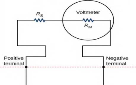
Analog meters use a galvanometer, which essentially consists of a coil of wire with a small resistance and a pointer with a scale attached. When current runs through the coil, the point turns; the amount the pointer turns is proportional to the amount of current running through the coil. Galvanometers can be used to make a voltmeter if a resistor is placed in series with the galvanometer. Consider a galvanometer that has a resistance of
The galvanometer is to be used to make an voltmeter that has a full scale reading of 10.00 V, as shown below. Recall that a voltmeter is connected in parallel with the component of interest, so the meter must have a high resistance or it will change the current running through the component, (a) What is the potential drop across the series resistor in the meter? (b) What is the resistance of the parallel resistor?
Av = lo.oo v →

Trending nowThis is a popular solution!

Chapter 10 Solutions
University Physics Volume 2
Additional Science Textbook Solutions
Essential University Physics: Volume 1 (3rd Edition)
Modern Physics
Sears And Zemansky's University Physics With Modern Physics
College Physics: A Strategic Approach (4th Edition)
Physics for Scientists and Engineers with Modern Physics
Physics: Principles with Applications


- When the switch is open in Figure 18.8, power Po is delivered to the resistor R1. When the switch is closed, which of the following is true about the power Pc delivered to R1? (Neglect the internal resistance of the battery.) (a) Pc Po (b) Pc = Po (c) Pc Po Figure 18.8 (Quick Quizzes 18.5 and 18.6)arrow_forwardThe values of the components in a simple series RC circuit containing a switch (Fig. P21.53) are C = 1.00 F, R = 2.00 106 , and = 10.0 V. At the instant 10.0 s after the switch is closed, calculate (a) the charge on the capacitor, (b) the current in the resistor, (c) the rate at which energy is being stored in the capacitor, and (d) the rate at which energy is being delivered by the battery.arrow_forwardWith the switch in the circuit of Figure 21.18a open, there is no current in R2. There is current in R1, however, and it is measured with the ammeter at the right side of the circuit. If the switch is closed (Fig. 21.18b), there is current in R2. What happens to the reading on the ammeter when the switch is closed? (a) The reading increases. (b) The reading decreases. (c) The reading does not change.arrow_forward
- Nichrome wire of cross-sectional radius 0.800 mm is to be used in winding a heating coil. If the coil must carry a current of 8.00 A when a voltage of 2.10 ✕ 102 V is applied across its ends, find the following. (a) the required resistance of the coil_______Ω(b) the length of wire you must use to wind the coil_______marrow_forwardA computer monitor uses 2.0 A of current when it is plugged into a 120 V outlet. Themonitor is never turned off. What is the yearly cost of operating the monitor if the cost of electricity is$0.12/kWh? [1 kWh = 3.6 x 10⁶ J](a) $14 (c) $98 (e) $250(b) $21 (d) $170 (It's e but I don't understand the explanation)arrow_forwardIn the figure R1 = 9.81 kΩ, R2 = 15.4 kΩ, C = 0.433 μF, and the ideal battery has emf ε = 18.0 V. First, the switch is closed a long time so that the steady state is reached. Then the switch is opened at time t = 0. What is the current in resistor 2 at t = 3.60 ms?arrow_forward
- 4. Given a DC battery of 12.0 volts connected to a single resistor of 3.00 Ohms. What current goes through the resistor? a. 12.0 A b. 36.0 A c. 3.00 A d. 4.00 A e. 16.7 Aarrow_forwardNichrome wire of cross-sectional radius 0.798 mm is to be used inwinding a heating coil. If the coil must carry a current of 8.73 A when a voltage of 1.3 x 10² V is applied across its ends, find:a) the required resistance of the coil and121.27Ω 147.46Ω 138.73Ω 11349Ωarrow_forwardWhen the switch S of the circuit in the figure is opened, the potential difference between points A and B is 3.08 V. After the switch is closed, the potential difference between points A and B decreases to 2.97 V and the current through the circuit is 1.00 mA. Determine the value of the resistance R1 in Ohms. choose the correct alternative: a) 2970 b) 11.00 c) 1.100 d) 110.0 e) 2.970arrow_forward
- In the figure below, let R = 7.00 Ω, L = 2.30 mH, and C = 1.65 µF. The circuit is a rectangular loop with a vertical wire in the middle that extends from the bottom side of the loop to almost reach the top side, ending at point b below the top side. The left side contains a battery of emf ℰ with the positive terminal above the negative terminal. The right side contains a capacitor C. The top side, from left to right, contains point a and a switch S in contact with point a. The vertical wire contains, from top to bottom, point b, an inductor L, and a resistor R. (a) Calculate the frequency of the damped oscillation of the circuit when the switch is thrown to position b. kHz(b) What is the critical resistance for damped oscillations? Ωarrow_forwardBased on your understanding of Ohm’s Law, electric power dissipation, and the relationship between length, cross section, and resistance; why do you think it is more efficient to operate electrical power lines at higher voltages? Can you think of any alternative methods for increasing the efficiency of power transmission?arrow_forwardA flashlight, which uses a 3.0 V battery, is turned on for 2.0 minutes. If the current in the flashlight is 100 mA, what is the energy dissipated? A. 121 J B. 9.0 J C. 72 J D. 36 Jarrow_forward
 Principles of Physics: A Calculus-Based TextPhysicsISBN:9781133104261Author:Raymond A. Serway, John W. JewettPublisher:Cengage Learning
 College PhysicsPhysicsISBN:9781285737027Author:Raymond A. Serway, Chris VuillePublisher:Cengage Learning
 College PhysicsPhysicsISBN:9781305952300Author:Raymond A. Serway, Chris VuillePublisher:Cengage Learning
 Physics for Scientists and EngineersPhysicsISBN:9781337553278Author:Raymond A. Serway, John W. JewettPublisher:Cengage Learning
 Physics for Scientists and Engineers with Modern ...PhysicsISBN:9781337553292Author:Raymond A. Serway, John W. JewettPublisher:Cengage Learning