
Videos
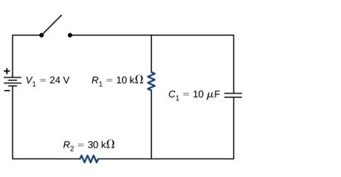
Consider the circuit below, (a) What is the initial current through resistor R2? when the switch is closed? (b) What is die current through resistor R2 when the capacitor
is fully charged, long after die switch is closed? (c) What happens if the switch is opened after it has been closed for some rime? (d) If the switch has been closed for a time period long enough for the capacitor to become fully charged, and then the switch is opened, how long before the current through resistor R1 reaches half of its initial value?

Trending nowThis is a popular solution!

Chapter 10 Solutions
University Physics Volume 2
Additional Science Textbook Solutions
University Physics with Modern Physics (14th Edition)
Essential University Physics (3rd Edition)
An Introduction to Thermal Physics
Introduction to Electrodynamics
College Physics
Life in the Universe (4th Edition)


- Consider a power plant is located 60 km away from a residential area uses Q-gauge (A=42.40mm2) wire ofcopper to transmit power at a current of I = 100.00 A.How much more power is dissipated in the copper wires than it would be in superconducting wires?arrow_forwardResistors are commonly rated at 18W,14W,12W ,1 W and 2 W for use in electrical circuits. If a current of1 = 2.00 A is accidentally passed through a R=1.00 resistor rated at 1 W, what would be the most probable outcome? Is there anything that can be done to prevent such an accident?arrow_forwardConsider the circuit below. The battery has an emf of = 30.00 V and an internal resistance of r = 1,00 . (a) Find the equivalent resistance of the circuit and the current out of the battery. (b) Find the current through each resistor, (c) Find die potential drop across each resistor, (d) Find the power dissipated by each resistor, (e) Find the total power supplied by the batteries.arrow_forward
- In the circuit below, it is known that R1 = 10 kΩ, R2 = 15 kΩ, and C = 0.4 μF, and a battery with an Emf of 20 Volts. Initially, the connector (switch) is connected for a long time until it reaches a steady state. Then the switch is disconnected/opened at t = 0. What is the current flowing in resistor 2 at t = 4 ms?arrow_forwardThree resistors of 25 Ω, 30 Ω and an unknown resistance R are connected in parallel and thecombination is connected to a 16 V source. If the total current delivered by the source is 1.5 A,determine the following:A. The value of R.B. The current in each resistor.C. Which resistor dissipates the highest power? Show your solution. Based on your answer,what conclusion can be made?arrow_forwardA battery is connected to a parallel-plate capacitor C through a resistor R as shown in the figure below, and left until the capacitor reaches its equilibrium charge. At time t=0, the two plates of the capacitor are pulled apart so that the separation d between them is doubled. Which graph shows the current I through the resistor as a function of time? [The arrow shows which direction is current is considered positive.] Thank you!arrow_forward
- The figure above shows a circuit containing an electromotive force (a battery), a capacitor with a capacitance of C farads (F), and a resistor with a resistance of R ohms (Omega). The voltage drop across the capacitor is Q/C, where Q is the charge (in coulombs), so in this case Kirchhoff's Law gives RI + (Q/C) = E(t) since the current is I = (dQ/dt), we have R(dQ/dt) + (1/C)Q= E(t) Suppose the resistance is 30 ohms, the capacitance is 0.1 Farads, a battery gives a constant voltage of 40 volts, and the initial charge is Q(0)=0C.Find the charge and the current at time t. Q(t)=? I(t)=?arrow_forwardA 3.50 μμF capacitor that is initially uncharged is connected in series with a 7.60 kΩ resistor and an emf source with E=185 V negligible internal resistance. Just after the circuit is completed, what is the voltage drop across the capacitor? Just after the circuit is completed, what is the voltage drop across the resistor? Just after the circuit is completed, what is the charge on the capacitor? Just after the circuit is completed, what is the current through the resistor?arrow_forwardA resistor of resistance R=9 and a resistor with variable resistance is connected to an ideal battery whose emf is =129V as shown in the figure below. The variable resistor is made up of a rectangular prism of a=7.7cm, b=2.81cm, L=50cm , and the material has resistivity =0.51 . The distance of the contact point from the edge can be adjusted to change the value of the resistance. For x=8.6cm find is the power dissipated on the resistor R. Express your final result with zero decimal places.arrow_forward
- A capacitor of capacitance C = 7.5 μF is initially uncharged. It is connected in series with a switch of negligible resistance, a resistor of resistance R = 11.5 kΩ, and a battery which provides a potential difference of VB = 110 V (a) Calculate the current I a very long time after the switch has been closed in A. (b) Calculate the time t after which the current through the resistor is one-third of its maximum value in s. (c) Calculate the charge Q on the capacitor when the current in the resistor equals one third its maximum value in C.arrow_forwardAt time t = 0, an RC circuit consists of a 14.0-V emf device, a 54.0-Ω resistor, and a 148.0-µF capacitor that is fully charged. The switch is thrown so that the capacitor begins to discharge. Time constant of the circuit is 0.007992s How much charge is stored by the capacitor at t = 0.5?, 2?, and 4??arrow_forwardWhat resistance, R, should be placed in series with the galvanometer, G, if it is to show a full deflection when the potential across the resistor is 6 V. The maximum current through the galvanometer is 250 mA and its internal resistance is 3 Ω. (a) 24 Ω (b) 23 Ω (c) 3 Ω (d) 5.25 Ω (e) 21arrow_forward

 Physics for Scientists and Engineers: Foundations...PhysicsISBN:9781133939146Author:Katz, Debora M.Publisher:Cengage Learning
 An Introduction to Physical SciencePhysicsISBN:9781305079137Author:James Shipman, Jerry D. Wilson, Charles A. Higgins, Omar TorresPublisher:Cengage Learning
 Principles of Physics: A Calculus-Based TextPhysicsISBN:9781133104261Author:Raymond A. Serway, John W. JewettPublisher:Cengage Learning