
Vector Mechanics for Engineers: Statics and Dynamics
12th Edition
ISBN: 9781259638091
Author: Ferdinand P. Beer, E. Russell Johnston Jr., David Mazurek, Phillip J. Cornwell, Brian Self
Publisher: McGraw-Hill Education
expand_more
expand_more
format_list_bulleted
Videos
Textbook Question
Chapter 10.1, Problem 10.42P
The position of boom ABC is controlled by the hydraulic cylinder BD. For the loading shown, determine the largest allowable value of the angle θ if the maximum force that the cylinder can exert on pin B is 25 kips.
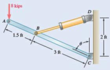
Fig. P10.41 and P10.42
Expert Solution & Answer
Want to see the full answer?
Check out a sample textbook solution
Students have asked these similar questions
For the steel truss and loading shown, determine the magnitude of the force (lb) of member BD, knowing that x = 14.1 ft, y = 7.6 ft, and P = 22538 lb. Round off only on the final answer expressed in 3 decimal places .
(a) Considering only buckling in the plane of the structure shown and using Euler’s formula, determine the value of θbetween 0 and 90° for which the allowable magnitude of the load P is maximum. (b) Determine the corresponding maximum value of P knowing that a factor of safety of 3.2 is required. Use E= 29 x 106 psi.
The pin at C is attached to member BCD and can slide along a slot cut in the fixed plate shown. Neglecting the effect of friction, derive an expression for the magnitude of the couple M required to maintain equilibrium when the force P that acts at D is directed (a) as shown, (b) vertically downward, (c) horizontally to the right.Fig. P10.18
Chapter 10 Solutions
Vector Mechanics for Engineers: Statics and Dynamics
Ch. 10.1 - Determine the vertical force P that must be...Ch. 10.1 - Determine the horizontal force P that must be...Ch. 10.1 - Prob. 10.3PCh. 10.1 - Prob. 10.4PCh. 10.1 - Prob. 10.5PCh. 10.1 - A spring of constant 15 kN/m connects points C and...Ch. 10.1 - The two-bar linkage shown is supported by a pin...Ch. 10.1 - Determine the weight W that balances the 10-lb...Ch. 10.1 - Prob. 10.9PCh. 10.1 - Prob. 10.10P
Ch. 10.1 - Solve Prob. 10.10, assuming that the force P...Ch. 10.1 - Prob. 10.12PCh. 10.1 - Prob. 10.13PCh. 10.1 - Prob. 10.14PCh. 10.1 - Prob. 10.15PCh. 10.1 - 10.15 and 10.16 Derive an expression for the...Ch. 10.1 - Prob. 10.17PCh. 10.1 - Prob. 10.18PCh. 10.1 - Prob. 10.19PCh. 10.1 - Prob. 10.20PCh. 10.1 - Prob. 10.21PCh. 10.1 - A couple M with a magnitude of 100 Nm isapplied as...Ch. 10.1 - Rod AB is attached to a block at A that can...Ch. 10.1 - Solve Prob. 10.23, assuming that the 800-N force...Ch. 10.1 - In Prob. 10.9, knowing that a = 42 in., b = 28...Ch. 10.1 - Determine the value of corresponding to...Ch. 10.1 - Prob. 10.27PCh. 10.1 - Determine the value of corresponding to...Ch. 10.1 - Prob. 10.29PCh. 10.1 - Two rods AC and CE are connected by a pin at Cand...Ch. 10.1 - Solve Prob. 10.30 assuming that force P is movedto...Ch. 10.1 - Prob. 10.32PCh. 10.1 - Prob. 10.33PCh. 10.1 - Prob. 10.34PCh. 10.1 - Prob. 10.35PCh. 10.1 - Prob. 10.36PCh. 10.1 - Prob. 10.37PCh. 10.1 - Prob. 10.38PCh. 10.1 - Prob. 10.39PCh. 10.1 - Prob. 10.40PCh. 10.1 - Prob. 10.41PCh. 10.1 - The position of boom ABC is controlled by...Ch. 10.1 - Prob. 10.43PCh. 10.1 - Prob. 10.44PCh. 10.1 - Prob. 10.45PCh. 10.1 - Prob. 10.46PCh. 10.1 - Denoting the coefficient of static friction...Ch. 10.1 - Prob. 10.48PCh. 10.1 - Prob. 10.49PCh. 10.1 - Prob. 10.50PCh. 10.1 - Prob. 10.51PCh. 10.1 - Prob. 10.52PCh. 10.1 - Prob. 10.53PCh. 10.1 - Prob. 10.54PCh. 10.1 - Prob. 10.55PCh. 10.1 - Prob. 10.56PCh. 10.1 - Prob. 10.57PCh. 10.1 - Determine the horizontal movement of joint C if...Ch. 10.2 - Using the method of Sec. 10.2C, solve Prob. 10.29....Ch. 10.2 - Prob. 10.60PCh. 10.2 - Prob. 10.61PCh. 10.2 - Prob. 10.62PCh. 10.2 - Prob. 10.63PCh. 10.2 - Prob. 10.64PCh. 10.2 - Prob. 10.65PCh. 10.2 - Using the method of Sec. 10.2C, solve Prob. 10.38....Ch. 10.2 - Prob. 10.67PCh. 10.2 - Prob. 10.68PCh. 10.2 - Prob. 10.69PCh. 10.2 - Prob. 10.70PCh. 10.2 - Prob. 10.71PCh. 10.2 - Prob. 10.72PCh. 10.2 - Prob. 10.73PCh. 10.2 - Prob. 10.74PCh. 10.2 - A load W of magnitude 144 lb is applied to...Ch. 10.2 - Solve Prob. 10.75, assuming that the spring...Ch. 10.2 - Bar ABC is attached to collars A and B that...Ch. 10.2 - Solve Prob. 10.77, assuming that the spring...Ch. 10.2 - Prob. 10.79PCh. 10.2 - Prob. 10.80PCh. 10.2 - Prob. 10.81PCh. 10.2 - A spring AB of constant k is attached to two...Ch. 10.2 - Prob. 10.83PCh. 10.2 - Prob. 10.84PCh. 10.2 - Prob. 10.85PCh. 10.2 - Prob. 10.86PCh. 10.2 - Prob. 10.87PCh. 10.2 - Prob. 10.88PCh. 10.2 - Prob. 10.89PCh. 10.2 - Prob. 10.90PCh. 10.2 - Prob. 10.91PCh. 10.2 - Prob. 10.92PCh. 10.2 - Prob. 10.93PCh. 10.2 - Prob. 10.94PCh. 10.2 - Prob. 10.95PCh. 10.2 - Prob. 10.96PCh. 10.2 - Bars AB and BC, each with a length l and of...Ch. 10.2 - Solve Prob. 10.97 knowing that l = 30 in. and k =...Ch. 10.2 - Bars AB and CD, each of length l and of negligible...Ch. 10.2 - Solve Prob. 10.99, assuming that the vertical...Ch. 10 - Determine the vertical force P that must be...Ch. 10 - Determine the couple M that must be applied...Ch. 10 - Prob. 10.103RPCh. 10 - Prob. 10.104RPCh. 10 - Prob. 10.105RPCh. 10 - Prob. 10.106RPCh. 10 - Prob. 10.107RPCh. 10 - Prob. 10.108RPCh. 10 - Prob. 10.109RPCh. 10 - Prob. 10.110RPCh. 10 - Prob. 10.111RPCh. 10 - Prob. 10.112RP
Knowledge Booster


Learn more about
Need a deep-dive on the concept behind this application? Look no further. Learn more about this topic, mechanical-engineering and related others by exploring similar questions and additional content below.Similar questions
- (a) Determine the maximum allowable horizontal span for a uniform cable with a weight per unit length of w if the tension in the cable is not to exceed a given value Tm. (b) Using the result of part a , determine the maximum span of a steel wire for which w = 0.25 lb/ft and Tm = 8000 lb.arrow_forwardSolve Prob. 10.108 assuming that the 24-lb load is applied at C instead of E.(Reference to Problem 10.108):Two identical rods ABC and DBE are connected by a pin at B and by a spring CE . Knowing that the spring is 4 in. long when unstretched and that the constant of the spring is 8 lb/in., determine the distance x corresponding to equilibrium when a 24-lb load is applied at E as shown.arrow_forwardSolve Prob. 6.97 assuming that the 75-kN load has been removed.(Reference to Problem 6.97):The cab and motor units of the front-end loader shown are connected by a vertical pin located 2 m behind the cab wheels. The distance from C to D is 1 m. The center of gravity of the 300-kN motor unit is located at Gm , while the centers of gravity of the 100-kN cab and 75-kN load are located, respectively, at Gc and GI. . Knowing that the machine is at rest with its brakes released, determine (a) the reactions at each of the four wheels, (b) the forces exerted on the motor unit at C and D.arrow_forward
- A spring of constant 15 kN/m connects points C and F of the linkage shown. Neglecting the weight of the spring and linkage, determine the force in the spring and the vertical motion of point G when a vertical downward 120-N force is applied (a) at point C ,( b) at points E and F.Fig. P10.8arrow_forwardKnowing that the average normal stress in member EF of the Pratt bridge truss shown must not exceed 8.36 ksi for the given loading, determine the cross-sectional area (in sq. in) of this member that will yield the most economical and safe design if h = 14.2 ft and P = 87.28 kips.arrow_forwardThe frictional resistance of a thrust bearing decreases as the shaft and bearing surfaces wear out. It is generally assumed that the wear is directly proportional to the distance traveled by any given point of the shaft and thus to the distance r from the point to the axis of the shaft. Assuming then that the normal force per unit area is inversely proportional to r , show that the magnitude M of the couple required to overcome the frictional resistance of a worn-out end bearing (with contact over the full circular area) is equal to 75 percent of the value given by Eq. (8.9) for a new bearing.arrow_forward
- A vibration isolation unit consists of two blocks of hard rubber with a modulus of rigidity G= 19 MPa bonded to a plate AB and to rigid supports as shown. Denoting by P the magnitude of the force applied to the plate and by δ the corresponding deflection, determine the effective spring constant, k 5 P/δ, of the system.arrow_forwardColumn ABC has a uniform rectangular cross section with b=12 mm and d=22 mm. The column is braced in the xz plane at its midpoint C and carries a centric load P of magnitude 3.8 kN. Knowing that a factor of safety of 3.2 is required, determine the largest allowable length L. Use E=200 GPaarrow_forwardEach of the five struts shown consists of a solid steel rod. (a) Know-ing that strut (1) is of a 0.8-in. diameter, determine the factor of safety with respect to buckling for the loading shown. (b) Determine the diameter of each of the other struts for which the factor of safety is the same as the factor of safety obtained in part a. Use E=29 *106 psiarrow_forward
- Problem # 8: The five forces acting at the end of the boom satisfy the condition of equilibrium. Determine the values of T_{1} and T_{2} .arrow_forwardThe center span of the Verrazano-Narrows Bridge consists of two uniform roadways suspended from four cables. The design of the bridge allows for the effect of extreme temperature changes that cause the sag of the center span to vary from hw= 386 ft in winter to hs= 394 ft in summer. Knowing that the span is L = 4260 ft, determine the change in length of the cables due to extreme temperature changes.arrow_forwardA load P is supported as shown by a steel pin that has been inserted in a short wooden member hanging from the ceiling. The ultimate strength of the wood used is 60 MPa in tension and 7.5 MPa in shear,while the ultimate strength of the steel is 145 MPa in shear. Knowing that b = 40 mm, c = 55 mm, and d = 12 mm, determine the load P if an overall factor of safety of 3.2 is desired.arrow_forward
arrow_back_ios
SEE MORE QUESTIONS
arrow_forward_ios
Recommended textbooks for you
 Elements Of ElectromagneticsMechanical EngineeringISBN:9780190698614Author:Sadiku, Matthew N. O.Publisher:Oxford University Press
 Mechanics of Materials (10th Edition)Mechanical EngineeringISBN:9780134319650Author:Russell C. HibbelerPublisher:PEARSON
 Thermodynamics: An Engineering ApproachMechanical EngineeringISBN:9781259822674Author:Yunus A. Cengel Dr., Michael A. BolesPublisher:McGraw-Hill Education
 Control Systems EngineeringMechanical EngineeringISBN:9781118170519Author:Norman S. NisePublisher:WILEY
 Mechanics of Materials (MindTap Course List)Mechanical EngineeringISBN:9781337093347Author:Barry J. Goodno, James M. GerePublisher:Cengage Learning
 Engineering Mechanics: StaticsMechanical EngineeringISBN:9781118807330Author:James L. Meriam, L. G. Kraige, J. N. BoltonPublisher:WILEY
Elements Of Electromagnetics
Mechanical Engineering
ISBN:9780190698614
Author:Sadiku, Matthew N. O.
Publisher:Oxford University Press
Mechanics of Materials (10th Edition)
Mechanical Engineering
ISBN:9780134319650
Author:Russell C. Hibbeler
Publisher:PEARSON
Thermodynamics: An Engineering Approach
Mechanical Engineering
ISBN:9781259822674
Author:Yunus A. Cengel Dr., Michael A. Boles
Publisher:McGraw-Hill Education
Control Systems Engineering
Mechanical Engineering
ISBN:9781118170519
Author:Norman S. Nise
Publisher:WILEY
Mechanics of Materials (MindTap Course List)
Mechanical Engineering
ISBN:9781337093347
Author:Barry J. Goodno, James M. Gere
Publisher:Cengage Learning
Engineering Mechanics: Statics
Mechanical Engineering
ISBN:9781118807330
Author:James L. Meriam, L. G. Kraige, J. N. Bolton
Publisher:WILEY
How to balance a see saw using moments example problem; Author: Engineer4Free;https://www.youtube.com/watch?v=d7tX37j-iHU;License: Standard Youtube License