
MECHANICS OF MTRLS(LL)-W/ACCESS>CUSTOM<
7th Edition
ISBN: 9781259713156
Author: BEER
Publisher: MCG CUSTOM
expand_more
expand_more
format_list_bulleted
Concept explainers
Videos
Textbook Question
Chapter 10.1, Problem 23P
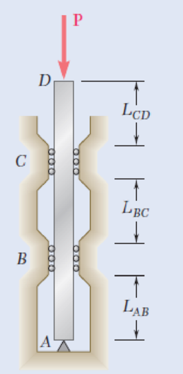
A 1-in.-square aluminum strut is maintained in the position shown by a pin support at A and by sets of rollers at B and C that prevent rotation of the strut in the plane of the figure. Knowing that LAB = 3 ft, LBC = 4 ft , and LCD = 1 ft, determine the allowable load P using a factor of safety with respect to buckling of 3.2. Consider only buckling in the plane of the figure and use E = 10.4 × 10⁶ psi.
Fig. P10.22 and P10.23
Expert Solution & Answer
Want to see the full answer?
Check out a sample textbook solution
Students have asked these similar questions
An aluminum strut 2.50m long has a rectangular section 60mm by 30mm. A bolt through each end secures the strut so that it acts as a hinged column about an axis perpendicular to the 60 mm dimension and as a fixed ended column about an axis perpendicular to the 30mm dimension. Determine the safe central load using a factor of safety of 2.5 and E = 70 Gpa.
A spreader bar is used in the assembly shown in the figure attached. It is made of a circular steel ros of diameter 32mm. Assuming that the cables and their connections are inextensible, determine largest load W that can be applied so that the spreader bar does not buckle. Both end of the spreader bar may be assumed to be pin connected. The youngs modulus of the spreader bar is, E = 200 x 10^3 N/mm^2.
A sign for an automobile service station is supported by two aluminum poles of hollow circular cross section, as shown in the figure. The poles are being designed to resist a wind pressure of 70 lb/ft^2 against the full area of the sign. The dimensions of the poles and sign are h1 = 16 ft, h2 = 7 ft, and b = 13 ft. To prevent buckling of the walls of the poles, the thickness t is specified as one tenth the outside diameter d.
(a) Determine the minimum required diameter of the poles based upon an allowable bending stress of 7100 psi in the aluminum. Round your answer to two decimal places.
d = ___ in.
(b) Determine the minimum required diameter based upon an allowable shear stress of 2100 psi. Round your answer to two decimal places.
d = ___ in.
Chapter 10 Solutions
MECHANICS OF MTRLS(LL)-W/ACCESS>CUSTOM<
Ch. 10.1 - Knowing that the spring at A is of constant k and...Ch. 10.1 - Two rigid bars AC and BC are connected by a pin at...Ch. 10.1 - 10.3 and 10.4 Two rigid bars AC and BC are...Ch. 10.1 - 10.3 and 10.4 Two rigid bars AC and BC are...Ch. 10.1 - The steel rod BC is attached to the rigid bar AB...Ch. 10.1 - The rigid rod AB is attached to a hinge at A and...Ch. 10.1 - The rigid bar AD is attached to two springs of...Ch. 10.1 - A frame consists of four L-shaped members...Ch. 10.1 - Determine the critical load of a pin-ended steel...Ch. 10.1 - Determine the critical load of a pin-ended wooden...
Ch. 10.1 - A column of effective length L can be made by...Ch. 10.1 - A compression member of 1.5-m effective length...Ch. 10.1 - Determine the radius of the round strut so that...Ch. 10.1 - Determine (a) the critical load for the square...Ch. 10.1 - A column with the cross section shown has a...Ch. 10.1 - A column is made from half of a W360 216...Ch. 10.1 - A column of 22-ft effective length is made by...Ch. 10.1 - A single compression member of 8.2-m effective...Ch. 10.1 - Knowing that P = 5.2 kN, determine the factor of...Ch. 10.1 - Members AB and CD are 30-mm-diameter steel rods,...Ch. 10.1 - The uniform brass bar AB has a rectangular cross...Ch. 10.1 - A 1-in.-square aluminum strut is maintained in the...Ch. 10.1 - A 1-in.-square aluminum strut is maintained in the...Ch. 10.1 - Column ABC has a uniform rectangular cross section...Ch. 10.1 - Column ABC has a uniform rectangular cross section...Ch. 10.1 - Column AB carries a centric load P of magnitude 15...Ch. 10.1 - Each of the five struts shown consists of a solid...Ch. 10.1 - A rigid block of mass m can be supported in each...Ch. 10.2 - An axial load P = 15 kN is applied at point D that...Ch. 10.2 - An axial load P is applied to the 32-mm-diameter...Ch. 10.2 - The line of action of the 310-kN axial load is...Ch. 10.2 - Prob. 32PCh. 10.2 - An axial load P is applied to the 32-mm-square...Ch. 10.2 - Prob. 34PCh. 10.2 - Prob. 35PCh. 10.2 - Prob. 36PCh. 10.2 - Solve Prob. 10.36, assuming that the axial load P...Ch. 10.2 - The line of action of the axial load P is parallel...Ch. 10.2 - Prob. 39PCh. 10.2 - Prob. 40PCh. 10.2 - The steel bar AB has a 3838-in. square cross...Ch. 10.2 - For the bar of Prob. 10.41, determine the required...Ch. 10.2 - A 3.5-m-long steel tube having the cross section...Ch. 10.2 - Prob. 44PCh. 10.2 - An axial load P is applied to the W8 28...Ch. 10.2 - Prob. 46PCh. 10.2 - A 100-kN axial load P is applied to the W150 18...Ch. 10.2 - A 26-kip axial load P is applied to a W6 12...Ch. 10.2 - Prob. 49PCh. 10.2 - Axial loads of magnitude P = 84 kN are applied...Ch. 10.2 - An axial load of magnitude P = 220 kN is applied...Ch. 10.2 - Prob. 52PCh. 10.2 - Prob. 53PCh. 10.2 - Prob. 54PCh. 10.2 - Axial loads of magnitude P = 175 kN are applied...Ch. 10.2 - Prob. 56PCh. 10.3 - Using allowable stress design, determine the...Ch. 10.3 - Prob. 58PCh. 10.3 - Prob. 59PCh. 10.3 - A column having a 3.5-m effective length is made...Ch. 10.3 - Prob. 61PCh. 10.3 - Bar AB is free at its end A and fixed at its base...Ch. 10.3 - Prob. 63PCh. 10.3 - Prob. 64PCh. 10.3 - A compression member of 8.2-ft effective length is...Ch. 10.3 - A compression member of 9-m effective length is...Ch. 10.3 - A column of 6.4-m effective length is obtained by...Ch. 10.3 - A column of 21-ft effective length is obtained by...Ch. 10.3 - Prob. 69PCh. 10.3 - Prob. 70PCh. 10.3 - Prob. 71PCh. 10.3 - Prob. 72PCh. 10.3 - Prob. 73PCh. 10.3 - For a rod made of aluminum alloy 2014-T6, select...Ch. 10.3 - Prob. 75PCh. 10.3 - Prob. 76PCh. 10.3 - A column of 4.6-m effective length must carry a...Ch. 10.3 - A column of 22.5-ft effective length must carry a...Ch. 10.3 - Prob. 79PCh. 10.3 - A centric load P must be supported by the steel...Ch. 10.3 - A square steel tube having the cross section shown...Ch. 10.3 - Prob. 82PCh. 10.3 - Prob. 83PCh. 10.3 - Two 89 64-mm angles are bolted together as shown...Ch. 10.3 - Prob. 85PCh. 10.3 - Prob. 86PCh. 10.3 - Prob. 87PCh. 10.3 - Prob. 88PCh. 10.4 - An eccentric load is applied at a point 22 mm from...Ch. 10.4 - Prob. 90PCh. 10.4 - Prob. 91PCh. 10.4 - Solve Prob. 10.91 using the interaction method and...Ch. 10.4 - A column of 5.5-m effective length is made of the...Ch. 10.4 - Prob. 94PCh. 10.4 - A steel compression member of 9-ft effective...Ch. 10.4 - Prob. 96PCh. 10.4 - Two L4 3 38-in. steel angles are welded together...Ch. 10.4 - Solve Prob. 10.97 using the interaction method...Ch. 10.4 - A rectangular column is made of a grade of sawn...Ch. 10.4 - Prob. 100PCh. 10.4 - Prob. 101PCh. 10.4 - Prob. 102PCh. 10.4 - Prob. 103PCh. 10.4 - Prob. 104PCh. 10.4 - A steel tube of 80-mm outer diameter is to carry a...Ch. 10.4 - Prob. 106PCh. 10.4 - Prob. 107PCh. 10.4 - Prob. 108PCh. 10.4 - Prob. 109PCh. 10.4 - Prob. 110PCh. 10.4 - Prob. 111PCh. 10.4 - Prob. 112PCh. 10.4 - Prob. 113PCh. 10.4 - Prob. 114PCh. 10.4 - Prob. 115PCh. 10.4 - A steel column of 7.2-m effective length is to...Ch. 10 - Determine (a) the critical load for the steel...Ch. 10 - Prob. 118RPCh. 10 - Prob. 119RPCh. 10 - (a) Considering only buckling in the plane of the...Ch. 10 - Member AB consists of a single C130 3 10.4 steel...Ch. 10 - The line of action of the 75-kip axial load is...Ch. 10 - Prob. 123RPCh. 10 - Prob. 124RPCh. 10 - A rectangular column with a 4.4-m effective length...Ch. 10 - Prob. 126RPCh. 10 - Prob. 127RPCh. 10 - Prob. 128RP
Knowledge Booster


Learn more about
Need a deep-dive on the concept behind this application? Look no further. Learn more about this topic, mechanical-engineering and related others by exploring similar questions and additional content below.Similar questions
- just final answer A rigid component ABC is supported by a pin-connected member (1). The member has a rectangular cross-section with dimensions of 54 mm and 48 mm. The elasticity modulus of the material is 169 GPa. If L1=2421 mm, L2=1226 mm, L3=2272 mm, and L4=2072 mm; Determine the maximum normal stress (MPa) in member (1) without buckling.arrow_forwardStatic Problem. Indications:The system shown is composed of an ABG bar, supported by a pin at point A and by a collarsmooth at point B (the collar slides on the bar ABG). The collar is pinned to the BDE bar, and theRod BDE is supported by a pin at D and a cable at end E.Based on the above, determine:a) The load P, such that the cable force EF is T.b) The internal loads in a section passing through point G (normal and shear force, and momentflexing).c) Draw bar BDE horizontally and generate the shear force and moment diagramsflexing Indicate the maximum values of shear force and bending moment and their location.?= 22 lb ? = 7 in ? = 6 inarrow_forwardA cantilever of 5 m length carries a uniformly distributed load of 4 kN/m over a length of 3 m from the fixed end, and a point load of 4 KN at the free end. draw S.F and B.M. diagrams of the cantileverarrow_forward
- Determine the critical axial buckling load for an 8 3/4 x 12 inches glue-laminated column braced at 10ft from the bottom in the y axis for a total height of 25ft. Assume pin connections at top and bottom. Fc= 1750 psi, E= 1.8x10⁶ psi. (Western cross-section glu-lam data is in the text).arrow_forwardMember AB consists of a single C130 x 10.4 steel channel of length 2.5 m. Knowing that the pins at A and B pass through the centroid of the cross section of the channel, determine the factor of safety for the load shown with respect to buckling in the plane of the figure when θ= 30°. Use Euler’s formula with E= 200 GPa.arrow_forwardA solid brass [E = 98 GPa] axial member is loaded and supported as shown. Segments (1) and (2) each have a diameter of 26 mm and segment (3) has a diameter of 12 mm. Assume L1 = 1.9 m, L2 = 1.3 m, L3 = 1.5 m, R = 40 kN, Q = 12 kN, and P = 22 kN. (a) Determine the axial force in section (1) section (2) and section (3) in kN. and the axial deformation of section (2) (b) Determine the deflection of joint D (positive if downward) with respect to the fixed support at A. in mm. (c) Determine the maximum normal stress in the entire axial member. Give answer in MPa.arrow_forward
- A 75 mm diameter compound bar is constructed by shrinking a circular brass bush onto the outside of a 50 mm diameter solid steel rod. If the compound bar is then subjected to an axial compressive load of 160 kN determine the load carried by the steel rod and the brass bush and the compressive stress set up in each material. For steel, E = 210 GN/m2; for brass, £ = 100 GN/m2arrow_forwardQ#3. An aluminium strut 16 ft long has a rectangular cross section 2 in by 3.5 in. A bolt through each end secure the strut in such a way that is acts as hinged column about an axis perpendicular to 3.5 in dimension; and as fixed column about an axis perpendicular to 2 in dimension. Determine the safe central load with a factor of safety of 2 and E= 10300000 psi. Also discuss in detail about the governing column capacity and reasons behind it.arrow_forwardA straight girder of uniform section and length L rests on supports at the ends, and is propped up by a third support in the middle. The weight of the girder and its load is w per unit length. If the central support does not yield, prove that it takes a load equal to (5/8)wL. ANSWER: 1.80cm and 2.48cm Please show solution to the answer.arrow_forward
- A steel [E = 25500 ksi] pipe column (1) with a cross-sectional area of A1 = 5.60 in.2 is connected at flange B to an aluminum alloy [E = 17500 ksi] pipe (2) with a cross-sectional area of A2 = 4.40 in.2. The assembly is connected to rigid supports at A and C. For the loading shown, determine the normal force in the steel pipe (1).arrow_forwardRigid bar ABC is supported by pin-connected bar (1). Bar (1) is 2.0-in. wide, 1.00-in. thick, and made of aluminum that has anelastic modulus of E = 12,000 ksi. Determine the maximum magnitude of load P that can be applied to the rigid bar withoutcausing member (1) to bucklearrow_forwardThe length of the rectangular arm, which is fixed at both ends, is L= 9 m, and the cross section is a=32 mm and b= 58 mm. Accordingly, find the possible buckling loads of the column and specify the maximum load that it can support. E=210 GPa (Fig. 3).arrow_forward
arrow_back_ios
SEE MORE QUESTIONS
arrow_forward_ios
Recommended textbooks for you
 Mechanics of Materials (MindTap Course List)Mechanical EngineeringISBN:9781337093347Author:Barry J. Goodno, James M. GerePublisher:Cengage Learning
Mechanics of Materials (MindTap Course List)
Mechanical Engineering
ISBN:9781337093347
Author:Barry J. Goodno, James M. Gere
Publisher:Cengage Learning
Column buckling; Author: Amber Book;https://www.youtube.com/watch?v=AvvaCi_Nn94;License: Standard Youtube License