ENGR.MECH.:STATICS-PACKAGE
14th Edition
ISBN: 9780134267029
Author: HIBBELER
Publisher: PEARSON
expand_more
expand_more
format_list_bulleted
Concept explainers
Videos
Textbook Question
Chapter 10.3, Problem 9P
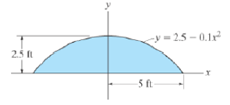
Solve the problem in two ways, using rectangular differential elements, (a) having a thickness dx and (b) having a thickness of dy.
Expert Solution & Answer
Want to see the full answer?
Check out a sample textbook solution
Students have asked these similar questions
The preliminary design of a large shaft connecting a motor with agenerator requires the use of a hollow shaft with inside and outside diameters4 in. and 6 in., respectively. Taking a safety factor of 2.5 andknowing that the shear resistance is 14 ksi, determine the maximumtorque that can be transmitted by the shaft as designed
A belt is to transmit 50 kW power to a machine. The sheave is 10 inches in diameter and turns at 1200 rpm, while the larger sheave turns at 500 rpm. Determine the design HP if a service factor of 1.35 and a correction factor of 0.85.
A solid steel shaft, whose Sy= 300 MPa and Su= 400 MPa, is used to transmit 3000 kW at 800 rpm. Determine its diameter.
Chapter 10 Solutions
ENGR.MECH.:STATICS-PACKAGE
Ch. 10.3 - Determine the moment of inertia of the shaded area...Ch. 10.3 - Determine the moment of inertia of the shaded area...Ch. 10.3 - Determine the moment of inertia of the shaded area...Ch. 10.3 - Determine the moment of inertia of the shaded area...Ch. 10.3 - Determine the moment of inertia about the x axis.Ch. 10.3 - Determine the moment of inertia about the y axis.Ch. 10.3 - Determine the moment of inertia for the shaded...Ch. 10.3 - Determine the moment of Inertia for the shaded...Ch. 10.3 - Determine the moment of inertia for the shaded...Ch. 10.3 - Determine the moment of inertia for the shaded...
Ch. 10.3 - Determine the moment of inertia for the shaded...Ch. 10.3 - Determine the moment of inertia for the shaded...Ch. 10.3 - Solve the problem in two ways, using rectangular...Ch. 10.3 - Determine the moment of inertia of the area about...Ch. 10.3 - Determine the moment of inertia for the shaded...Ch. 10.3 - Determine the moment of inertia for the shaded...Ch. 10.3 - Determine the moment of inertia about the x axis.Ch. 10.3 - Determine the moment of inertia about the y axis.Ch. 10.3 - Determine the moment of inertia for the shaded...Ch. 10.3 - Determine the moment of inertia for the shaded...Ch. 10.3 - Determine the moment of inertia for the shaded...Ch. 10.3 - Determine the moment of inertia for the shaded...Ch. 10.3 - Determine the moment of inertia for the shaded...Ch. 10.3 - Determine the moment of inertia for the shaded...Ch. 10.3 - Determine the moment of inertia for the shaded...Ch. 10.3 - Determine the moment of inertia for the shaded...Ch. 10.3 - Prob. 23PCh. 10.3 - Determine the moment of inertia for the shaded...Ch. 10.4 - Determine the moment of inertia of the beams...Ch. 10.4 - Determine the moment of inertia of the beams...Ch. 10.4 - Determine me moment of inertia of the...Ch. 10.4 - Determine the moment of inertia of the...Ch. 10.4 - Determine the moment of inertia of the composite...Ch. 10.4 - Determine the moment of inertia of the composite...Ch. 10.4 - The moment of inertia about the y axis is 264...Ch. 10.4 - Determine the location y of the centroid of the...Ch. 10.4 - Determine,y, which locates the centroidal axis x...Ch. 10.4 - Determine the moment of inertia for the beams...Ch. 10.4 - Determine the moment of inertia for the beams...Ch. 10.4 - Determine the moment of inertia Ix of the shaded...Ch. 10.4 - Determine the moment of inertia Ix of the shaded...Ch. 10.4 - Determine the moment of inertia of the beams...Ch. 10.4 - Determine, g, which locates the centroidal axis z...Ch. 10.4 - Determine the moment of inertia about the x axis.Ch. 10.4 - Prob. 37PCh. 10.4 - Determine the moment of inertia of the shaded area...Ch. 10.4 - Determine the moment of inertia of the shaded area...Ch. 10.4 - Prob. 40PCh. 10.4 - Prob. 41PCh. 10.4 - Determine the moment of inertia of the beams...Ch. 10.4 - Prob. 43PCh. 10.4 - Prob. 44PCh. 10.4 - Determine the distance x to the centroid C of the...Ch. 10.4 - Determine the moment of inertia for the shaded...Ch. 10.4 - Determine the moment of inertia for the shaded...Ch. 10.4 - Determine the moment of inertia of the...Ch. 10.4 - Determine the moment of inertia of the...Ch. 10.4 - Prob. 50PCh. 10.4 - Determine the moment of inertia for the beams...Ch. 10.4 - Determine the moment of inertia of the area about...Ch. 10.4 - Determine the moment of inertia of the area about...Ch. 10.7 - Determine the product of inertia of the thin strip...Ch. 10.7 - Determine the product of inertia of the shaded...Ch. 10.7 - Determine the product of inertia for the shaded...Ch. 10.7 - Determine the product of inertia of the shaded...Ch. 10.7 - Determine the product of inertia for the parabolic...Ch. 10.7 - Prob. 59PCh. 10.7 - Determine the product of inertia of the shaded...Ch. 10.7 - Prob. 61PCh. 10.7 - Prob. 62PCh. 10.7 - Prob. 63PCh. 10.7 - Determine the product of inertia for the beams...Ch. 10.7 - Determine the product of inertia tor the shaded...Ch. 10.7 - Determine the product of inertia of the cross...Ch. 10.7 - Determine the location (xy) to the centroid C of...Ch. 10.7 - For the calculation, assume all comers to be...Ch. 10.7 - Determine the moments of inertia Iu, Iv and the...Ch. 10.7 - Prob. 70PCh. 10.7 - using Mohrs circle Hint. To solve find the...Ch. 10.7 - Prob. 72PCh. 10.7 - using Mohrs circle.Ch. 10.7 - Prob. 74PCh. 10.7 - using Mohrs circle.Ch. 10.7 - Prob. 76PCh. 10.7 - using Mohrs circle.Ch. 10.7 - Prob. 78PCh. 10.7 - using Mohrs circle.Ch. 10.7 - Prob. 80PCh. 10.7 - Solve Prob. 10-80 using Mohrs circle.Ch. 10.7 - Prob. 82PCh. 10.7 - Solve Prob. 10-82 using Mohrs circle.Ch. 10.8 - Determine the moment of inertia of the thin ring...Ch. 10.8 - The material has a constant density .Ch. 10.8 - Determine the radius of gyration kx of the...Ch. 10.8 - Prob. 87PCh. 10.8 - Hint: For integration, use thin plate elements...Ch. 10.8 - The material has a constant density .Ch. 10.8 - Prob. 90PCh. 10.8 - Determine the moment of inertia Iy. The specific...Ch. 10.8 - Prob. 92PCh. 10.8 - Prob. 93PCh. 10.8 - The total mass of the solid is 1500 kg.Ch. 10.8 - The slender rods have a mass of 4 kg/ point A....Ch. 10.8 - and a 4-kg slender rod. Determine the radius of...Ch. 10.8 - The material has a density of 200kg/m3. Prob....Ch. 10.8 - Determine the location y of the center of mass G...Ch. 10.8 - Prob. 99PCh. 10.8 - The pendulum consists of a plate having a weight...Ch. 10.8 - 15 lb. and 20 lb, respectively, determine the mass...Ch. 10.8 - The density of the material is 7.85 Mg/m3.Ch. 10.8 - Prob. 103PCh. 10.8 - Determine its mass moment of inertia about the y...Ch. 10.8 - Prob. 105PCh. 10.8 - Prob. 106PCh. 10.8 - Prob. 107PCh. 10.8 - The thin plate has a mass of 12 kg/m2. Determine...Ch. 10.8 - The material has a density of 200kg/m3.Ch. 10.8 - Determine the moment of inertia for the shaded...Ch. 10.8 - Determine the moment of inertia for the shaded...Ch. 10.8 - Determine the area moment of inertia of the shaded...Ch. 10.8 - Prob. 4RPCh. 10.8 - Determine the area moment of inertia of the...Ch. 10.8 - Determine the product of inertia of the shaded...
Knowledge Booster


Learn more about
Need a deep-dive on the concept behind this application? Look no further. Learn more about this topic, mechanical-engineering and related others by exploring similar questions and additional content below.Similar questions
- The machine is designed to be powered by a 100 HP electric motor at a speed of 1500 rpm, with standard D-120 V-belts. The pitch diameter of the smaller sheave is 101.6 mm and the bigger sheave is 406.4 mm. Service factor is 1.25. Use length of D-120 V-belt equal to 123.3 inches. Determine the center distance between sheaves in mm; the arc of contact in deg; and the design in HP.arrow_forwardsolve/ show solution for given answer equations kb = (Ab*Eb)/ g and kc = (Ac*Ec) / g G is the approximate effective lengtharrow_forwardWrite legibly, provide manual step by step solution, and diagram for below given problem. A hollow shaft that has 110mm outside diameter and 80mm inside diameter is used to transmit 120kw at 500rpm. Determine the shaft stress. Ans.12.18MPa.arrow_forward
- Design a typical rigid flange coupling for connecting a motor and a centrifugal pump shafts. The coupling needs to transmit 15 KW at 1000 rpm. The allowable shear stresses of the shaft, key and bolt materials are 60 MPa, 50 MPa and 25 MPa respectively. The shear modulus of the shaft material may be taken as 84GPa. The angle of twist of the shaft should be limited to 1 degree in 20 times the shaft diameter. Note: show complete solutionarrow_forwardsingle plate clutch with both sides of the plate effective. The axial. Pressure being limited to 0.13 N/ mm. the outer diameter of the contact surface is (250mm) and the inner diameter (150 mm). the M=0.3 find the power transmitted by clutch at (500r.p.m). Assuming uniform weararrow_forwardThe module and the number of teeth on the pinion of a spur gear are 12mm and 15teeth respectively.A power of 400kW is to be transmitted at 1700rpm of width.if the involute teeth are of standard proportions (addendum=m) with the pressure angle of 22.5° determine (A) torque due to power delivered (B) tangential load (C) teeth width (E)load on the bearingsarrow_forward
- A transmission shaft, supporting two pulleys A and B and mounted between two bearings C1 and C2 is shown in Fig. Power is transmitted from pulley A to B. The shaft is made of plain carbon steel 45C8 (Sut = 600 and Syt = 380 N/mm2). The pulleys are keyed to the shaft. Determine the shaft diameter using the ASME code if, kb=1.5 and kt=1.0arrow_forwardPlease full answer A) Explain 1) Different types of Keys 2) Interference fit 3) Couplings. B) A simply supported shaft is shown in the following Figure. A constant magnitude distributed unit load p is applied as the shaft rotates. The shaft is also subject to a steady torque of Tmax = 2000 N-m., find the diameter of shaft required to obtain a safety factor of 2.5 in fatigue loading if the shaft is steel of Sut = 814 MPa and Sy = 703 MPa. The dimensions are in cm, the distributed force in N/cm, and the torque is in N-m. No stress concentrations are present, the shaft is machined, the required reliability is 90%, and the shaft operates at room temperature.arrow_forwardThis engine is used in a hoist. Motor 2.5 kWwith the help of gears with a power of and n = 500 rpm.transmits. If the shear strength of the AB shaft is τa = 160 MPa;a) Find the diameter of AB shaft with 1.4 times safety.b) Find the maximum force F the engine can carry.arrow_forward
- A V-belt drive transmits 20kW from an electric motor running at 1440rpm to the main shaft of a roving machine. The motor and main shaft pulleys have 300 & 600 rpm respectively. The coefficient of friction between belt and pulley is 0.25. The centre distance between the shafts is 1000mm. The top width, thickness, section angle and density of belt and permissible tension on the belt are 22mm, 14mm and 40deg, 0.97gcm-2 and 600N respectively. How many belts are needed? Calculate the length of a belt neededarrow_forwardA bushed pin type flexible coupling is used to transmit 10 kW power at 720 rpm. The design torque is 150% of rated torque. The keys have square cross-section. The permissible stresses are: For shaft and key material, τ = 66.67 N/mm2 , σc = 200 N/mm2 ; For pin material, τ = 35 N/mm2 , σt = 133 N/mm2 ; For flange material τ = 16.67 N/mm2 . The permissible bearing pressure for rubber bushes is 1 N/mm2. The number of bushes is 4. Design the bushed pin flexible coupling. Explain Axle, Spindle, Counter shaft and line-shaft with their examples .arrow_forwardA bushed pin type flexible coupling is used to transmit 10 kW power at 720 rpm. The design torque is 150% of rated torque. The keys have square cross-section. The permissible stresses are: For shaft and key material, τ = 66.67 N/mm2, σc = 200 N/mm2; For pin material, τ = 35 N/mm2, σt = 133 N/mm2; For flange material τ = 16.67 N/mm2. The permissible bearing pressure for rubber bushes is 1 N/mm2. The number of bushes is 4. Design the bushed pin flexible coupling.arrow_forward
arrow_back_ios
SEE MORE QUESTIONS
arrow_forward_ios
Recommended textbooks for you
 Elements Of ElectromagneticsMechanical EngineeringISBN:9780190698614Author:Sadiku, Matthew N. O.Publisher:Oxford University Press
 Mechanics of Materials (10th Edition)Mechanical EngineeringISBN:9780134319650Author:Russell C. HibbelerPublisher:PEARSON
 Thermodynamics: An Engineering ApproachMechanical EngineeringISBN:9781259822674Author:Yunus A. Cengel Dr., Michael A. BolesPublisher:McGraw-Hill Education
 Control Systems EngineeringMechanical EngineeringISBN:9781118170519Author:Norman S. NisePublisher:WILEY
 Mechanics of Materials (MindTap Course List)Mechanical EngineeringISBN:9781337093347Author:Barry J. Goodno, James M. GerePublisher:Cengage Learning
 Engineering Mechanics: StaticsMechanical EngineeringISBN:9781118807330Author:James L. Meriam, L. G. Kraige, J. N. BoltonPublisher:WILEY
Elements Of Electromagnetics
Mechanical Engineering
ISBN:9780190698614
Author:Sadiku, Matthew N. O.
Publisher:Oxford University Press
Mechanics of Materials (10th Edition)
Mechanical Engineering
ISBN:9780134319650
Author:Russell C. Hibbeler
Publisher:PEARSON
Thermodynamics: An Engineering Approach
Mechanical Engineering
ISBN:9781259822674
Author:Yunus A. Cengel Dr., Michael A. Boles
Publisher:McGraw-Hill Education
Control Systems Engineering
Mechanical Engineering
ISBN:9781118170519
Author:Norman S. Nise
Publisher:WILEY
Mechanics of Materials (MindTap Course List)
Mechanical Engineering
ISBN:9781337093347
Author:Barry J. Goodno, James M. Gere
Publisher:Cengage Learning
Engineering Mechanics: Statics
Mechanical Engineering
ISBN:9781118807330
Author:James L. Meriam, L. G. Kraige, J. N. Bolton
Publisher:WILEY
Mechanical Design (Machine Design) Clutches, Brakes and Flywheels Intro (S20 ME470 Class 15); Author: Professor Ted Diehl;https://www.youtube.com/watch?v=eMvbePrsT34;License: Standard Youtube License