
Videos
a.
The value of
a.
Answer to Problem 11.43P
Explanation of Solution
Given:
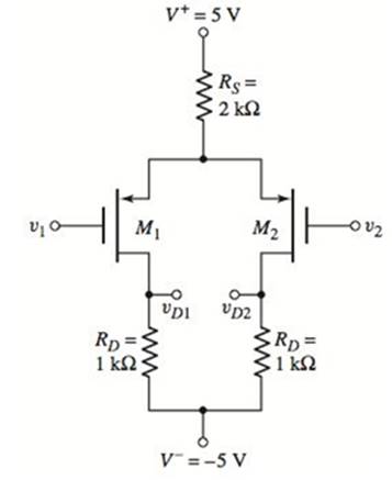
The given circuit is,

Calculation:
Consider the given figure,
Let equate the voltages,
Hence,
b.
The value of
b.
Answer to Problem 11.43P
Explanation of Solution
Given:
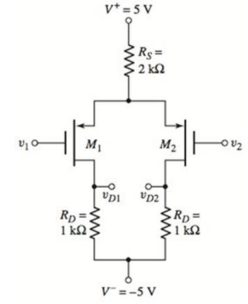
The given circuit is,

Calculation:
Consider the given figure,
Let equate the voltages,
Hence,
c.
The value of
c.
Answer to Problem 11.43P
Explanation of Solution
Given:
The given circuit is,
Calculation:
Consider the given figure,
Let equate the voltages,
Hence,
d.
The value of
d.
Answer to Problem 11.43P
Explanation of Solution
Given:
The given circuit is,
Calculation:
Consider the given figure,
Let equate the voltages,
Hence,
Want to see more full solutions like this?
Chapter 11 Solutions
Microelectronics Circuit Analysis and Design


- The equation of an angle-modulated voltage is v = 10 sin (l08t + 3 sin 104,). What form of angle modulation is this? Calculate the carrier and modulating frequencies, the modulation index and deviation, and the power dissipated in a 100-ohm resistor.arrow_forwardFor a mosfet amplifier circuit, how can I choose an input and output capacitor with poles at 10Hz and 100Hz? Where RC = 1/w.arrow_forwardQ2. An FM transmitter is modulated with a single tone A, cos (2nA2t) and a carrier amplitude of A, volt. The output resistive load for no modulation is A, N and the modulation constant k, = A5 Hz / volt. For the given parameters, determine the following: 1- The average power in all sidebands. 2- The carrier power if the amplitude of modulating signal is reduced by 5 volts.arrow_forward
- Bandwidth beta=250Hz, center frequency f0=750Hz of the band-proof circuit consisting of serial LCis desired.If the capacitor value is 100nF, what should the R and L values be?arrow_forwardi) A communication system employs a continuous source. The channel noise is white and Gaussian. The bandwidth of the source output is 10 MHz and signal to noise power ratio at the receiver is 100. (a) Determine the channel capacity. (b) If the signal to noise ratio drops to 10, how much bandwidth is needed to achieve the same channel capacity as in (a). (c) If the bandwidth is decreased to 1 MHz, what S/N ratio is required to maintain the same channel capacity as in (a).arrow_forwarda. An AM transmitter has the unmodulated carrier power of 20kW and can be modulated to a maximum of 70% before the system saturates/overloads. Find the value to which carrier power can be increased if 40% modulation limit is imposed.b. An analog communication system using FM has the highest modulating frequency of 5 kHz and maximum deviation of 25 kHz. Calculate the bandwidth of modulated signal using Carson’s rule. Compare this value with the one obtained using the simple formula. For practical systems which of these values should be used?arrow_forward
- Message sign; m (t) = 10sinc (400 * t), and carrier sign; c (t) = 100cos (2 * pi * f * t) modulates by phase modulation. Modulation index 6, message bandwidth W = 200 Hz. • Obtain the mathematical expression of the phase modulated sign, u (t). • What is the maximum phase deviation of the modulated signal? • What is the strength of the modulated signal?arrow_forward20.a. A –3.8 dBm optical signal exits an amplifier with a signal strength of 15.1 dBm. How much gain does this amplifier provide?A. 15.1 dBB. 11.3 dBC. 18.9 dBD. 13.8 dB20.b. You need to reduce the signal strength in a fiber optic cable before the signal is sent to a receiver. Which piece of equipment would you use for this?A. WDMB. Optical switchC. Optical attenuatorD. Optical couplerarrow_forwardif the parameters for the BJT given Beta=120, VBE=0.7V, VT=26mV, VA=infinityarrow_forward
- 14.a. While conducting an OTDR trace, you find that the signal strength drops by 0.091 dB over an 82 m section of fiber. What's the attenuation in this fiber?A. 0.80 dB/kmB. 7.46 dB/kmC. 0.91 dB/kmD. 1.11 dB/km14.b. Which component converts an optical signal into an electrical signal in a transceiver?A. LEDB. EDFAC. Optical modemD. Photodiodearrow_forwardElectronic Since k = 0.35x10^3, VGSQ = 6.2 V, VGS(Th) = 2.4 V, RF = 100 MΩ, RG = 10 MΩ, RD = 7.6 kΩ, RS = 2.2 kΩ and RL = 21 kΩ in the circuit in the figure, the output voltage In which option is the amplitude value (Vout) given correctly? NOTE-1: E-MOSFET output impedance is rd = 70 kΩ and should be taken into account in calculations. NOTE-2: Capacitors are of negligible size at mid-band frequency. NOTE-3: It is within the 5 kHz mid-band frequency.arrow_forwardfT = 500 MHz, rx = 300 Ω, Cμ = 0.60 pF for the BJT, and CGS = 3 pF and CGD = 0.60 pF for the FET. Derive an expression for the total input capacitance of the BJT as shown looking into node υb. Assume CL = 0. Use it to interpret Eq. (17.138).arrow_forward
 Introductory Circuit Analysis (13th Edition)Electrical EngineeringISBN:9780133923605Author:Robert L. BoylestadPublisher:PEARSON
 Delmar's Standard Textbook Of ElectricityElectrical EngineeringISBN:9781337900348Author:Stephen L. HermanPublisher:Cengage Learning
 Programmable Logic ControllersElectrical EngineeringISBN:9780073373843Author:Frank D. PetruzellaPublisher:McGraw-Hill Education
 Fundamentals of Electric CircuitsElectrical EngineeringISBN:9780078028229Author:Charles K Alexander, Matthew SadikuPublisher:McGraw-Hill Education
 Electric Circuits. (11th Edition)Electrical EngineeringISBN:9780134746968Author:James W. Nilsson, Susan RiedelPublisher:PEARSON
 Engineering ElectromagneticsElectrical EngineeringISBN:9780078028151Author:Hayt, William H. (william Hart), Jr, BUCK, John A.Publisher:Mcgraw-hill Education,