
Applied Statics and Strength of Materials (6th Edition)
6th Edition
ISBN: 9780133840728
Author: Limbrunner
Publisher: PEARSON
expand_more
expand_more
format_list_bulleted
Videos
Textbook Question
Chapter 11, Problem 11.49SP
The rod shown is firmly attached to rigid supports. If there is initially no stress in the rod, compute the stress in each material if the temperature drops by
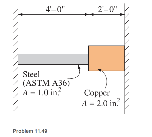
Expert Solution & Answer
Want to see the full answer?
Check out a sample textbook solution
Students have asked these similar questions
When a cable has a diameter of 1.51 inches2 and extends from point C to point D, find the tension in the cord and compute the stress caused by the cable. Neglect the members' weight and friction.
the compund bar, composed of the three segsemnt shown, is initially stree-free. a.) compute the stress in aluminum segment if the temperature drops at 25 degrees. b) compute the force resisted by the steel. c) compute the stress in the steel. d) compute the stress in bronze. assume that the walls do not yield and use the following data
For the given load, find the value of the stress amplitude and stress ratio respectively,
Chapter 11 Solutions
Applied Statics and Strength of Materials (6th Edition)
Ch. 11 - Prob. 11.1PCh. 11 - A rectangular ASTM A36 steel bar 2 in. by 6 in. in...Ch. 11 - Calculate Poisson’s ratio for a cast iron that has...Ch. 11 - Modulus of elasticity, modulus of rigidity, and...Ch. 11 - Compute all the dimensional changes for the steel...Ch. 11 - A surveyor’s steel tape is exactly 100ft long...Ch. 11 - An aluminum wire is stretched between two rigid...Ch. 11 - Prob. 11.8PCh. 11 - A concrete roadway pavement is placed in 60ftlong...Ch. 11 - Prob. 11.10P
Ch. 11 - A 4in. -by- 8in . short wood post is reinforced on...Ch. 11 - A short post. 150mm by 150mm , of Douglas fir, is...Ch. 11 - The cables of a power line are copper-coated steel...Ch. 11 - Prob. 11.14PCh. 11 - For the short column shown, assuming that lateral...Ch. 11 - A 1.0 -in.-diameter hole is drilled on the...Ch. 11 - Prob. 11.17PCh. 11 - A long, flat steel bar 4 in. wide and 38 thick is...Ch. 11 - A long, flat steel bar 5 in. wide and 38 thick has...Ch. 11 - 11.20 An aluminum specimen of circular cross...Ch. 11 - Prob. 11.21PCh. 11 - Prob. 11.22PCh. 11 - 11.23 A concrete cylinder, -in, in diameter, was...Ch. 11 - Prob. 11.24PCh. 11 - For the element of Problem 11.24: a. Locate the...Ch. 11 - Prob. 11.26CPCh. 11 - Prob. 11.27CPCh. 11 - Prob. 11.28CPCh. 11 - Prob. 11.29CPCh. 11 - A 50 -mm-diameter ASTM A36 steel rod is subjected...Ch. 11 - A 4 -ft-long square ASTM A36 steel bar, 2 in. by 2...Ch. 11 - A concrete test cylinder is 150 mm in diameter and...Ch. 11 - A 14 -in.-long steel rod, 112 in diameter, was...Ch. 11 - Determine the change in the diameter of an ASTM...Ch. 11 - 11.35 The steel bar shown in Figure 11.3 (see...Ch. 11 - Compute the change in the thickness of the ASTM...Ch. 11 - The steel rails of a railroad track are laid in...Ch. 11 - A rolled brass rod and a steel rod are secured to...Ch. 11 - 11.39 A -m-long steel member is set snugly between...Ch. 11 - 11.40 The distance between two fixed points on a...Ch. 11 - A steel truss is loaded as shown. The...Ch. 11 - 11.42 For the truss of Problem 5.25, the members...Ch. 11 - A surveyor’s steel tape has a cross-sectional area...Ch. 11 - A 1 -in.-diameter ASTM A36 steel tie rod, 30 ft...Ch. 11 - 11.45 A copper wire is held taut between two...Ch. 11 - 11.46 A horizontal steel member is anchored at...Ch. 11 - 11.47 Three vertical steel wires are loaded as...Ch. 11 - 11.48 Assume for Problem 11.47 that the same load...Ch. 11 - The rod shown is firmly attached to rigid...Ch. 11 - 11.50 A structural steel bar mm in width and mm...Ch. 11 - A redwood timber member having a 16 -in.-square...Ch. 11 - A steel pipe has an outside diameter of 12 in. and...Ch. 11 - A short 14 -in.-square concrete pier is reinforced...Ch. 11 - An ASTM A36 steel rod, 375.06 mm long and having a...Ch. 11 - An aluminum rod with an area of 1.5in.2 and an...Ch. 11 - A solid brass cylinder with a cross-sectional area...Ch. 11 - Three 14 in.-diameter wires are symmetrically...Ch. 11 - Rework Problem 11.57 with outer wires of aluminum,...Ch. 11 - Three rods support a weight, as shown. The...Ch. 11 - A flat steel bar 4 in. wide and 12 thick must be...Ch. 11 - A 19 -mm-diameter hole is drilled on the...Ch. 11 - A flat bar is 38 thick and has a centrally located...Ch. 11 - A long, flat steel bar 125 mm wide and 10 mm thick...Ch. 11 - 11.64 A short -in.-diameter compression member is...Ch. 11 - Prob. 11.65SPCh. 11 - 11.66 A rectangular block of wood, in. by in. in...Ch. 11 - 11.67 A -mm-diameter rod is subjected to an axial...Ch. 11 - The rectangular plate shown is subjected to a...Ch. 11 - A wood block, subjected to a tensile load, fails...Ch. 11 - Prob. 11.70SPCh. 11 - A shaft in a speed-reduction mechanism is loaded...Ch. 11 - An axially loaded 50 -mm-by- 75 -mm steel bar has...
Knowledge Booster


Learn more about
Need a deep-dive on the concept behind this application? Look no further. Learn more about this topic, mechanical-engineering and related others by exploring similar questions and additional content below.Similar questions
- Answer the following: Determine the force (in KN) exerted on the wall due to chnage in temperature? What is the stress (in MPa) in the bronze member? What is the stress ( in MPa) in the Copper member? NOTE: include the free body diagaram.arrow_forwardanswer the following: Determine the force (in kN) exerted on the wall due to change in temperature? What is the stress (in MPa) in the Steel member? What is the stress (in MPa) in the Bronze member? What is the stress (in MPa) in the Copper member? NOTE: indicate the free body diagram.arrow_forwardSOLVE FOR 30 MINUTES FREE BODY DIAGRAM AND SOLVE FOR STRESS IN THE CABLEarrow_forward
- Calculate the maximum and minimum normal stresses experienced by the lever indicated in the image.arrow_forwardAn aluminum rod is rigidly attached between a steel rod and a bronze as shown. Axial loads are applied at the positions indicated. Find the stress of each rod in MPa. Then what type of stress?arrow_forwardThe lap joint shown is fastened by five ¾ inch-diameter rivets. The bearing stress in the plates is limited to 10 ksi and the shearing stress in the rivets is 15 ksi. Assume the applied load is equally distributed among the five rivets. The thickness of each plate is ½ in. Calculate the load P based on each stress given. Determine the maximum safe load P that can be applied. Express the loads in kips.arrow_forward
- When the stress conditions are given as shown below, calculate the vertical stress and shear stress acting on the ab face.arrow_forwardThe homogeneous bar ABC is supported by a pin at C and a cable that runs from A to B around the frictionless pulley at D. Find the stress (in psi) in the cable if its diameter is d = 0.51 in and the weight of the bar is 5298 lb. Round off the final answer to three decimal places.arrow_forwardDetermine the largest weight “W” that can be supported by the two wires AB and AC. The working stresses are 100MPa for AB and 150MPa for AC. The cross sectional area of AB and AC are 400mm2 and 200mm2 Compute “W” due to the stress capacity of AB Compute “W” due to the stress capacity of AC. Determine the safest value of “W”.arrow_forward
- The relationship where the stress is linear up to the proportional limitarrow_forwardThe bolt shown on the picture is subjected to total tensile force of 90 kN. Determine the tensile stress at the body of the bolt and tensile stress at root of bolt. Find also the compressive stress at the head as the bolt bears on the surface to resist the tensile load.arrow_forwardThe homogeneous bar ABC is supported by a pin at C and a cable that runs from A to B around the frictionless pulley at D. Find the stress (in psi) in the cable if its diameter is d = 0.55 in and the weight of the bar is 5391 lb. Round off the final answer to 3 decimal places.arrow_forward
arrow_back_ios
SEE MORE QUESTIONS
arrow_forward_ios
Recommended textbooks for you
 Elements Of ElectromagneticsMechanical EngineeringISBN:9780190698614Author:Sadiku, Matthew N. O.Publisher:Oxford University Press
 Mechanics of Materials (10th Edition)Mechanical EngineeringISBN:9780134319650Author:Russell C. HibbelerPublisher:PEARSON
 Thermodynamics: An Engineering ApproachMechanical EngineeringISBN:9781259822674Author:Yunus A. Cengel Dr., Michael A. BolesPublisher:McGraw-Hill Education
 Control Systems EngineeringMechanical EngineeringISBN:9781118170519Author:Norman S. NisePublisher:WILEY
 Mechanics of Materials (MindTap Course List)Mechanical EngineeringISBN:9781337093347Author:Barry J. Goodno, James M. GerePublisher:Cengage Learning
 Engineering Mechanics: StaticsMechanical EngineeringISBN:9781118807330Author:James L. Meriam, L. G. Kraige, J. N. BoltonPublisher:WILEY
Elements Of Electromagnetics
Mechanical Engineering
ISBN:9780190698614
Author:Sadiku, Matthew N. O.
Publisher:Oxford University Press
Mechanics of Materials (10th Edition)
Mechanical Engineering
ISBN:9780134319650
Author:Russell C. Hibbeler
Publisher:PEARSON
Thermodynamics: An Engineering Approach
Mechanical Engineering
ISBN:9781259822674
Author:Yunus A. Cengel Dr., Michael A. Boles
Publisher:McGraw-Hill Education
Control Systems Engineering
Mechanical Engineering
ISBN:9781118170519
Author:Norman S. Nise
Publisher:WILEY
Mechanics of Materials (MindTap Course List)
Mechanical Engineering
ISBN:9781337093347
Author:Barry J. Goodno, James M. Gere
Publisher:Cengage Learning
Engineering Mechanics: Statics
Mechanical Engineering
ISBN:9781118807330
Author:James L. Meriam, L. G. Kraige, J. N. Bolton
Publisher:WILEY
An Introduction to Stress and Strain; Author: The Efficient Engineer;https://www.youtube.com/watch?v=aQf6Q8t1FQE;License: Standard YouTube License, CC-BY