
Introductory Circuit Analysis; Laboratory Manual For Introductory Circuit Analysis Format: Kit/package/shrinkwrap
13th Edition
ISBN: 9780134297446
Author: Boylestad, Robert L.
Publisher: Prentice Hall
expand_more
expand_more
format_list_bulleted
Videos
Textbook Question
Chapter 11, Problem 11P
For the circuit of Fig. 11.78 composed of standard values:
a. Determine the time constant.
b. Write the mathematical expression for the current iL after the switch is closed.
c. Repeat part (b) for VL and VR
d. Determine iL and VL at one, three, and five time constants.
e. Sketch the waveforms of iL, vL and vR.
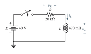
Fig. 11.78
Expert Solution & Answer
Want to see the full answer?
Check out a sample textbook solution
Students have asked these similar questions
In the circuit below, if the inductance L is large enough to operate in continuous current mode.
a) Draw the waveform of the output voltage and mains current for the 45 degree trigger angle when the switch S is in transmission.
b) Average value of output DA voltage VDC1 when switch S is open, output DA when switch S is closed (in transmission) If the average value of the voltage is VDC2, calculate the value of VDC1 / VDC2.
Lesson: power electronics
please quick
An alternating voltage is represented by the expression v = 35 sin (314.2 t) volt. Determine, i) the maximum value,
ii) the frequency,
iii) the period of the waveform, and
iv) the value 3.5 ms after it passes through zero, going positive.
(b) i. Explain the types of semiconductors and the classifications of the semiconductor materials. ii. With the aid of a diagram, explain the formation of the P and N types of semiconductor.
Find value of voltage induced in a coil.
if a coil has 780 turns and a constant flux of 7mWb and a changing flux of 13mWb.
Chapter 11 Solutions
Introductory Circuit Analysis; Laboratory Manual For Introductory Circuit Analysis Format: Kit/package/shrinkwrap
Ch. 11 - For the electromagnet in Fig. 11.75: a. Find the...Ch. 11 - For the inductor in Fig. 11.76, find the...Ch. 11 - a. Repeat Problem 2 with a ferromagnetic core with...Ch. 11 - For the inductor in Fig. 11.77, find the...Ch. 11 - An air-core inductor has a total inductance of 4.7...Ch. 11 - What are the inductance and the range of expected...Ch. 11 - If the flux linking a coil of 50 turns changes at...Ch. 11 - Determine the rate of change of flux linking a...Ch. 11 - How many turns does a coil have if 42 mV are...Ch. 11 - Find the voltage induced across a coil of 22 mH if...
Ch. 11 - For the circuit of Fig. 11.78 composed of standard...Ch. 11 - For the circuit in Fig. 11.79 composed of standard...Ch. 11 - For the network of Fig. 11.80. a. Write the...Ch. 11 - Give a supply of 18 V, use standard values to...Ch. 11 - For the circuit in Fig. 11.82: a. Write the...Ch. 11 - In this problem, the effect of reversing the...Ch. 11 - For the network of Fig. 11.84: a. Find the...Ch. 11 - Prob. 18PCh. 11 - Prob. 19PCh. 11 - Prob. 20PCh. 11 - For the network in Fig. 11.88: a. Determine the...Ch. 11 - For the network in Fig. 11.89: a. Write the...Ch. 11 - Prob. 23PCh. 11 - For Fig. 11.91: a. Determine the mathematical...Ch. 11 - For Fig. 11.92: a. Determine the mathematical...Ch. 11 - For the network in Fig. 11.93, the switch is...Ch. 11 - The switch in Fig. 11.94 has been open for a long...Ch. 11 - Prob. 28PCh. 11 - The switch for the network in Fig. 11.96 has been...Ch. 11 - The switch in Fig. 11.97 has been closed for a...Ch. 11 - Given iL=100mA(1e-t/20ms) a. Determine iLatt=1ms....Ch. 11 - a. If the measured current for an inductor during...Ch. 11 - The network in Fig. 11.98 employs a DMM with an...Ch. 11 - Find the waveform for the voltage induced across a...Ch. 11 - Find the waveform for the voltage induced across a...Ch. 11 - Prob. 36PCh. 11 - Find the total inductance of the circuit of Fig....Ch. 11 - Find the total inductance for the network of Fig....Ch. 11 - Reduce the network in Fig. 11.104 to the fewest...Ch. 11 - Reduce the network in Fig. 11.105 to the fewest...Ch. 11 - Reduce the network of Fig. 11.106 to the fewest...Ch. 11 - For the network in Fig. 11.107: a. Write the...Ch. 11 - For the network in Fig. 11.108: a. Write the...Ch. 11 - For the network in Fig. 11.109. a. Find the...Ch. 11 - Find the steady-state currents I1 and I2 for the...Ch. 11 - Find the steady-state currents and voltages for...Ch. 11 - Find the steady-state currents and voltages for...Ch. 11 - Find the indicated steady-state currents and...Ch. 11 - Prob. 49PCh. 11 - Using PSpice or Multisim, verify the results of...Ch. 11 - Using the PSpice or Multisim, find the solution to...Ch. 11 - Using PSpice or Multisim, find the solution to...Ch. 11 - Using PSpice or Multisim, verify the results of...
Knowledge Booster


Learn more about
Need a deep-dive on the concept behind this application? Look no further. Learn more about this topic, electrical-engineering and related others by exploring similar questions and additional content below.Similar questions
- What unit do we use to report coupling constants (aka J-values)? a) MHz b) Hz c) ppm d) %arrow_forwardThree phase Bridge rectifier operated from a 380V, 50Hz source throughout three-phase Y/Y connected transformer with ration 2:1. The load current has continuous character with negligible ripples and average thyristor current of 15A. The circuit inductance per phase is 1.2mH. The rectified voltage due to overlapping angle is 90 % of that voltage when this angle is neglected. 1- How much will the voltage drop be due to circuit inductance * 2- How much will the dc average voltage Vdc(alpha) be. 3- How much will the firing angle be ? 4- The overlapping angle. 5- How much is the percentage change of the output dc power if the thyristors T2, T4 and T6 are replaced by three diodes D2, D4, D6. 6- How much will be the maximum RMS phase current for the mentioned in previous task circuit ( semi-converter). 7- If an additional of 1 mH inductances are added to the existing inductances in the phases , how much will the overlapping angle be. The dc load current is kept constant & the…arrow_forwardWhen the waveform shown in fig. (1) is applied to true responding ac voltmeter, the output would be (5.314 V). If the same signal is applied to average responding ac voltmeter, what will be: 1. The indicate value. 2. The true value. 3. The true form factor. 4. The indicate crest factor.arrow_forward
- Q7: A: Find each of the following values, F, Vrms, Vde? B: Find the instantaneous voltage at time t = 0.01secarrow_forwardA relay has a 500-turn coil that draws 50 mA rms when a 60-Hz voltage of 24 V rms is applied. Assume that the resistance of the coil is negligible. Determine the peak flux linking the coil, the reluctance of the core, and the inductance of the coil.arrow_forwardMagnetically coupled circuit examplearrow_forward
- Explore the concept of power quality in electrical systems and the various disturbances and issues that can affect it, such as voltage sags, harmonics, and flicker.arrow_forwardA typical “deep-cycle” battery (used for electric trolling motors for fishing boats) is capable of delivering 12 V and 5 A for a period of 10 hours. How much charge flows through the battery in this interval? How much energy is delivered by the battery?arrow_forwardBakshi electrical machines sourcearrow_forward
- A machine coil has a resistance of 46 ohms at 25 degrees celsius. Its temperature coefficient of resistance is 0.0045454 at 20 degrees celsius. At what temperature will its resistance be at 105 ohmsarrow_forwardQ/ A three stage Cockroft-Walton generator is supplied by 212.133 V, 50 Hz source via a transformer with turns ratio equals to 2/800. All capacitors have a value of (0.8 μF). The protection current equals to 15 mA. Find the following: a. Find the output peak voltage that is used for testing without considering the voltage drop. b. Find the output peak voltage that is used for testing with considering the voltage drop. c. What is the ripple voltage? d. If the lowest capacitor is increased to twice its value, what is the output peak voltage that is used for testing with considering the voltage drop. e. Comparing the results of ( b ) and ( d ) above , do you recommend doubling the value of the lowest capacitor or not? f. According to the circuit values, is the 3 stages represents the optimum number of stages for this generator?arrow_forwardWith frequency f= 500 cycles/sec, what is the pure element in series with the R=25 ohms which causes the current to lags the voltage by 20 deg?arrow_forward
arrow_back_ios
SEE MORE QUESTIONS
arrow_forward_ios
Recommended textbooks for you
 Introductory Circuit Analysis (13th Edition)Electrical EngineeringISBN:9780133923605Author:Robert L. BoylestadPublisher:PEARSON
 Delmar's Standard Textbook Of ElectricityElectrical EngineeringISBN:9781337900348Author:Stephen L. HermanPublisher:Cengage Learning
 Programmable Logic ControllersElectrical EngineeringISBN:9780073373843Author:Frank D. PetruzellaPublisher:McGraw-Hill Education
 Fundamentals of Electric CircuitsElectrical EngineeringISBN:9780078028229Author:Charles K Alexander, Matthew SadikuPublisher:McGraw-Hill Education
 Electric Circuits. (11th Edition)Electrical EngineeringISBN:9780134746968Author:James W. Nilsson, Susan RiedelPublisher:PEARSON
 Engineering ElectromagneticsElectrical EngineeringISBN:9780078028151Author:Hayt, William H. (william Hart), Jr, BUCK, John A.Publisher:Mcgraw-hill Education,
Introductory Circuit Analysis (13th Edition)
Electrical Engineering
ISBN:9780133923605
Author:Robert L. Boylestad
Publisher:PEARSON
Delmar's Standard Textbook Of Electricity
Electrical Engineering
ISBN:9781337900348
Author:Stephen L. Herman
Publisher:Cengage Learning
Programmable Logic Controllers
Electrical Engineering
ISBN:9780073373843
Author:Frank D. Petruzella
Publisher:McGraw-Hill Education
Fundamentals of Electric Circuits
Electrical Engineering
ISBN:9780078028229
Author:Charles K Alexander, Matthew Sadiku
Publisher:McGraw-Hill Education
Electric Circuits. (11th Edition)
Electrical Engineering
ISBN:9780134746968
Author:James W. Nilsson, Susan Riedel
Publisher:PEARSON
Engineering Electromagnetics
Electrical Engineering
ISBN:9780078028151
Author:Hayt, William H. (william Hart), Jr, BUCK, John A.
Publisher:Mcgraw-hill Education,
How do Universal Motors work ?; Author: Lesics;https://www.youtube.com/watch?v=0PDRJKz-mqE;License: Standard Youtube License