
Introductory Circuit Analysis; Laboratory Manual For Introductory Circuit Analysis Format: Kit/package/shrinkwrap
13th Edition
ISBN: 9780134297446
Author: Boylestad, Robert L.
Publisher: Prentice Hall
expand_more
expand_more
format_list_bulleted
Videos
Textbook Question
Chapter 11, Problem 15P
For the circuit in Fig. 11.82:
a. Write the mathematical expressions for the current iL and the voltage vL following the closing of the switch. Note the magnitude and the direction of the initial current.
b. Sketch the waveform of iL and vL for the entire period from initial value to steady-state level.
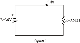
Fig. 11.82
Expert Solution & Answer

Trending nowThis is a popular solution!

Students have asked these similar questions
Two electric devices A and B are connected in parallel, and the rms current in A is 15 amp. If the current in B lags behind A by π/3 radians and the total line current is 23.4 amp. (rms), determine the current in B.
For the circuit in fig .11.82
A. Write the mathematical expressions for the current IL and the voltage Vl following the closing of the switch.
B. Sketch the waveform of iL and VL for the entire period from initial value to steady-state level.
Determine the following:(a) The components present in the circuit. (b) The rms value of the current. (c) The rms value of the voltage.
Chapter 11 Solutions
Introductory Circuit Analysis; Laboratory Manual For Introductory Circuit Analysis Format: Kit/package/shrinkwrap
Ch. 11 - For the electromagnet in Fig. 11.75: a. Find the...Ch. 11 - For the inductor in Fig. 11.76, find the...Ch. 11 - a. Repeat Problem 2 with a ferromagnetic core with...Ch. 11 - For the inductor in Fig. 11.77, find the...Ch. 11 - An air-core inductor has a total inductance of 4.7...Ch. 11 - What are the inductance and the range of expected...Ch. 11 - If the flux linking a coil of 50 turns changes at...Ch. 11 - Determine the rate of change of flux linking a...Ch. 11 - How many turns does a coil have if 42 mV are...Ch. 11 - Find the voltage induced across a coil of 22 mH if...
Ch. 11 - For the circuit of Fig. 11.78 composed of standard...Ch. 11 - For the circuit in Fig. 11.79 composed of standard...Ch. 11 - For the network of Fig. 11.80. a. Write the...Ch. 11 - Give a supply of 18 V, use standard values to...Ch. 11 - For the circuit in Fig. 11.82: a. Write the...Ch. 11 - In this problem, the effect of reversing the...Ch. 11 - For the network of Fig. 11.84: a. Find the...Ch. 11 - Prob. 18PCh. 11 - Prob. 19PCh. 11 - Prob. 20PCh. 11 - For the network in Fig. 11.88: a. Determine the...Ch. 11 - For the network in Fig. 11.89: a. Write the...Ch. 11 - Prob. 23PCh. 11 - For Fig. 11.91: a. Determine the mathematical...Ch. 11 - For Fig. 11.92: a. Determine the mathematical...Ch. 11 - For the network in Fig. 11.93, the switch is...Ch. 11 - The switch in Fig. 11.94 has been open for a long...Ch. 11 - Prob. 28PCh. 11 - The switch for the network in Fig. 11.96 has been...Ch. 11 - The switch in Fig. 11.97 has been closed for a...Ch. 11 - Given iL=100mA(1e-t/20ms) a. Determine iLatt=1ms....Ch. 11 - a. If the measured current for an inductor during...Ch. 11 - The network in Fig. 11.98 employs a DMM with an...Ch. 11 - Find the waveform for the voltage induced across a...Ch. 11 - Find the waveform for the voltage induced across a...Ch. 11 - Prob. 36PCh. 11 - Find the total inductance of the circuit of Fig....Ch. 11 - Find the total inductance for the network of Fig....Ch. 11 - Reduce the network in Fig. 11.104 to the fewest...Ch. 11 - Reduce the network in Fig. 11.105 to the fewest...Ch. 11 - Reduce the network of Fig. 11.106 to the fewest...Ch. 11 - For the network in Fig. 11.107: a. Write the...Ch. 11 - For the network in Fig. 11.108: a. Write the...Ch. 11 - For the network in Fig. 11.109. a. Find the...Ch. 11 - Find the steady-state currents I1 and I2 for the...Ch. 11 - Find the steady-state currents and voltages for...Ch. 11 - Find the steady-state currents and voltages for...Ch. 11 - Find the indicated steady-state currents and...Ch. 11 - Prob. 49PCh. 11 - Using PSpice or Multisim, verify the results of...Ch. 11 - Using the PSpice or Multisim, find the solution to...Ch. 11 - Using PSpice or Multisim, find the solution to...Ch. 11 - Using PSpice or Multisim, verify the results of...
Knowledge Booster


Learn more about
Need a deep-dive on the concept behind this application? Look no further. Learn more about this topic, electrical-engineering and related others by exploring similar questions and additional content below.Similar questions
- A 70-Vac source has the following waveform. Determine:a. equation of the waveform (in time domain)b. the instantaneous voltage when t = 120 msc. the angle (1st occurrence) after t = 0 when the voltage is +80 Vd. the time (2nd occurrence) after t = 0 when the voltage is –10 Varrow_forwardElectrical load that draws current whose impedance varies throughout the cycle of the input ac voltage waveform is known as nonlinear load. True Falsearrow_forwardCalculate the rms value of a sinusoidal current of maximum value of 20 Aarrow_forward
- A 1000-W electric motor is connected to a 120 V rms, 60-Hz source. The power factor seen by the source is 0.8, lagging. To correct the pf to 0.95 lagging, a capacitor is placed in parallel with the motor. Calculate the current drawn from the source with and without the capacitor connected. Determine the value of the capacitor required to make the correction.arrow_forwardSolve for 20 V rms supply. Thank you.arrow_forwardA 50-cycle voltage with maximum value of 24 V. (a) What will be the value of the instantaneous voltage at 0.00175 sec after the wave passesthrough in positive direction? (b) what will be the equation of the instantaneous current, if a non-inductive resistor of 9 ohms is connectedto the voltage source?arrow_forward
- Your company has been chosen to supply a 50 Hz alternator to a European utility. The stator is wye connected with each phase winding having 36 turns of wire. The rotor is supplying 0.127 Wb of flux in the center of pole face. What is the rms value of the output voltage if measured line to linearrow_forwardCompute the instantaneous power absorbed by the inductance at t = 2 ms.arrow_forwardSuppose for designing a diesel engine power plant you have brought a diesel engine & an 8 pole Alternator which have flux per pole of 0.045Wb. Turn per phases of the alternator is 150. The engine is so run that the speed of the engine which is coupled to the Alternator is 750 rpm. Determine the frequency and value of induced voltage/phase.arrow_forward
- electric units a & b are connected in parallel and its rms current is 15A. If the current in b lags behind a by pi/3 rads and the current is 23.4 A. find the current in b and sketch the equivalent circuit diagramarrow_forward1) 169sin 377t a) What is the RMS value? b) What is the Average value?arrow_forwardAn ac generator with a maximum voltage of 24.0 V and a frequency of 60.0 Hz is connected to a resistor with a resistanceR = 265 Ω. Find (a) the rms voltage and (b) the rms current in the circuit. In addition, determine (c) the average powerand (d) the maximum power dissipated in the resistor.arrow_forward
arrow_back_ios
SEE MORE QUESTIONS
arrow_forward_ios
Recommended textbooks for you
 Introductory Circuit Analysis (13th Edition)Electrical EngineeringISBN:9780133923605Author:Robert L. BoylestadPublisher:PEARSON
 Delmar's Standard Textbook Of ElectricityElectrical EngineeringISBN:9781337900348Author:Stephen L. HermanPublisher:Cengage Learning
 Programmable Logic ControllersElectrical EngineeringISBN:9780073373843Author:Frank D. PetruzellaPublisher:McGraw-Hill Education
 Fundamentals of Electric CircuitsElectrical EngineeringISBN:9780078028229Author:Charles K Alexander, Matthew SadikuPublisher:McGraw-Hill Education
 Electric Circuits. (11th Edition)Electrical EngineeringISBN:9780134746968Author:James W. Nilsson, Susan RiedelPublisher:PEARSON
 Engineering ElectromagneticsElectrical EngineeringISBN:9780078028151Author:Hayt, William H. (william Hart), Jr, BUCK, John A.Publisher:Mcgraw-hill Education,
Introductory Circuit Analysis (13th Edition)
Electrical Engineering
ISBN:9780133923605
Author:Robert L. Boylestad
Publisher:PEARSON
Delmar's Standard Textbook Of Electricity
Electrical Engineering
ISBN:9781337900348
Author:Stephen L. Herman
Publisher:Cengage Learning
Programmable Logic Controllers
Electrical Engineering
ISBN:9780073373843
Author:Frank D. Petruzella
Publisher:McGraw-Hill Education
Fundamentals of Electric Circuits
Electrical Engineering
ISBN:9780078028229
Author:Charles K Alexander, Matthew Sadiku
Publisher:McGraw-Hill Education
Electric Circuits. (11th Edition)
Electrical Engineering
ISBN:9780134746968
Author:James W. Nilsson, Susan Riedel
Publisher:PEARSON
Engineering Electromagnetics
Electrical Engineering
ISBN:9780078028151
Author:Hayt, William H. (william Hart), Jr, BUCK, John A.
Publisher:Mcgraw-hill Education,
How do Universal Motors work ?; Author: Lesics;https://www.youtube.com/watch?v=0PDRJKz-mqE;License: Standard Youtube License