SHIGLEY'S MECH.ENGR...(LL)-PKG.>CUSTOM<
10th Edition
ISBN: 9781260028379
Author: BUDYNAS
Publisher: MCG/CREATE
expand_more
expand_more
format_list_bulleted
Concept explainers
Videos
Textbook Question
Chapter 11, Problem 30P
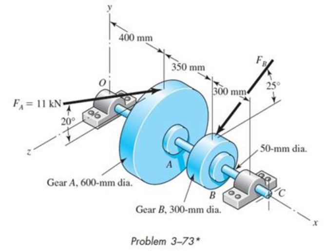
Repeat the requirements of Prob. 11-29 for the bearing at the left end of the shaft.
11-29* The shaft shown in the figure is proposed as a preliminary design for the application defined in Prob. 3-73, p. 152. The effective centers of the gears for force transmission are shown. The dimensions for the bearing surfaces (indicated with cross markings) have been estimated. The shaft rotates at 900 rev/min, and the desired bearing life is 12 kh with a 98 percent reliability in each bearing, assuming distribution data from manufacturer 2 in Table 11-6. Use an application factor of 1.2.
- (a) Obtain a Basic Load Rating for a ball bearing at the right end.
Expert Solution & Answer
Want to see the full answer?
Check out a sample textbook solution
Students have asked these similar questions
A three-thread worm gear, rotating at 1000 rpm, drives a 31-tooth worm gear and transmit 15 HP. Theworm has 14 ½ o teeth with ¾ pitch, 2 in pitch diameter, and an included face angle of 60o. The coefficientof friction is 0.05. (Assume Y = 0.322)
A. Determine the helix angle of the worm. Ans. 70.30o
B. Determine the speed ratio. Ans. 10.33C. Determine the center distance. Ans. 4.70 inD. Determine the apparent stress in the worm wheel teeth. Ans. 31,100 psiE. Determine the efficiency of this worm-gear set. Ans. 85.70%
A pair of 20º full depth involute teeth bevel gears connect two shafts at right angles having velocity ratio 3 : 1. The gear is made of cast iron having allowable static stress as 70 MPa and the 20teeth pinion is of steel with allowable static stress as 100 MPa and 200BHN. The pinion works at 750 r.p.m. Determine the maximum power can be transmitted by the gears if the module is 10mm. Kf=1.4
A short stub shaft, made of SAE 1035, as rolled, receivers 30 hp at 300 rpm via a 12-in. spur gear, the power being delivered to another shaft through a flexible coupling. The gear is keyed (profile keyway) midway between the bearings. The pressure angle of the gear teeth 20o, N = 1.5 based on the octahedral shear stress theory with varying stresses. (a) Neglecting the radial component R of the tooth load W , determine the shaft diameter. (b) Considering both the tangential and the radial components, compute the shaft diameters. (c) Is the difference in the results of the parts (a) and (b) enough to change your choice of the shaft size?
Chapter 11 Solutions
SHIGLEY'S MECH.ENGR...(LL)-PKG.>CUSTOM<
Ch. 11 - Manufacturer Rating Life, Revolutions Weibull...Ch. 11 - Manufacturer Rating Life, Revolutions Weibull...Ch. 11 - Manufacturer Rating Life, Revolutions Weibull...Ch. 11 - Problems 112 and 113 raise the question of the...Ch. 11 - Prob. 5PCh. 11 - Manufacturer Rating Life, Revolutions Weibull...Ch. 11 - Two ball bearings from different manufacturers are...Ch. 11 - 11-8 to 11-13 For the bearing application...Ch. 11 - 11-8 to 11-13 For the bearing application...Ch. 11 - 11-8 to 11-13 For the bearing application...
Ch. 11 - 11-8 to 11-13 For the bearing application...Ch. 11 - 11-8 to 11-13 For the bearing application...Ch. 11 - 11-8 to 11-13 For the bearing application...Ch. 11 - A countershaft carrying two V-belt pulleys is...Ch. 11 - A countershaft carrying two V-belt pulleys is...Ch. 11 - A countershaft carrying two V-belt pulleys is...Ch. 11 - A countershaft carrying two V-belt pulleys is...Ch. 11 - For the shaft application defined in Prob. 3-77,...Ch. 11 - For the shaft application defined in Prob. 3-79,...Ch. 11 - An 02-series single-row deep-groove ball bearing...Ch. 11 - An 02-series single-row deep-groove ball bearing...Ch. 11 - 11-22 to 11-26 An 02-series single-row deep-groove...Ch. 11 - 1122 to 1126 An 02-series single-row deep-groove...Ch. 11 - 1122 to 1126 An 02-series single-row deep-groove...Ch. 11 - 1122 to 1126 An 02-series single-row deep-groove...Ch. 11 - 1122 to 1126 An 02-series single-row deep-groove...Ch. 11 - The shaft shown in the figure is proposed as a...Ch. 11 - Repeat the requirements of Prob. 11-27 for the...Ch. 11 - The shaft shown in the figure is proposed as a...Ch. 11 - Repeat the requirements of Prob. 11-29 for the...Ch. 11 - Shown in the figure is a gear-driven squeeze roll...Ch. 11 - The figure shown is a geared countershaft with an...Ch. 11 - The figure is a schematic drawing of a...Ch. 11 - A gear-reduction unit uses the countershaft...Ch. 11 - The worm shaft shown in part a of the figure...Ch. 11 - In bearings tested at 2000 rev/min with a steady...Ch. 11 - A 16-tooth pinion drives the double-reduction...Ch. 11 - Estimate the remaining life in revolutions of an...Ch. 11 - The same 02-30 angular-contact ball bearing as in...Ch. 11 - A countershaft is supported by two tapered roller...Ch. 11 - For the shaft application defined in Prob. 3-74,...Ch. 11 - For the shaft application defined in Prob. 3-76,...Ch. 11 - Prob. 43PCh. 11 - The gear-reduction unit shown has a gear that is...
Knowledge Booster


Learn more about
Need a deep-dive on the concept behind this application? Look no further. Learn more about this topic, mechanical-engineering and related others by exploring similar questions and additional content below.Similar questions
- campute the bending stress number for the goer pair described by the given data beLow. KS= 1, Km= 1,21, F= 2.00 in, DP= 3,33 in, NG= 70, Np=20 hp = 1750v. p.m, Av=11, Pd =6, Tp= 900ib V1= 1527 ft/min The matarial used for pinion a gear is cast ironarrow_forwardA steel shaft 800 mm long transmitting 15 kW at 400 r.p.m. is supported at two bearings at the twoends. A gear wheel having 80 teeth and 500 mm pitch circle diameter is mounted at 200 mm from theleft hand side bearing and receives power from a pinion meshing with it. The axis of pinion and gearlie in the horizontal plane. A pulley of 300 mm diameter is mounted at 200 mm from right hand sidebearing and is used for transmitting power by a belt. The belt drive is inclined at 30° to the vertical inthe forward direction. The belt lap angle is 180 degrees. The coefficient of friction between belt andpulley is 0.3. Design and sketch the arrangement of the shaft assuming the values of safe stresses as :τ = 55 MPa; σt= 80 MPa. Take torsion and bending factor 1.5 and 2 respectively.arrow_forwardA single stage spur gear gearbox has a module of 1.5mm and an input speed of 1500.p.m. and a pinion with 15 teeth. The overall ratio of the gearbox is 6:1 and the gearbox is transmitting a power of 6000W. If the factor of safetv is to be reduced to an absolute minimum acceptable value and the gears are to be made from a material with a Yield stress of 540 MPa, what is the face width of the gears (in mm) Express your answer in the form 21.00 ie with two decimal place an no unitsarrow_forward
- A helical cast steel gear with 30o helix angle has to transmit 35 kW at 2000 rpm. If the gears has 25 teeth, find the necessary module, pitch diameters and face width for 20o full depth involute teeth. The static stress for cast steel may be taken as 100 MPa. The face width may be taken as 3 times to normal pitch. The tooth form factor is given by the expression y'= 0.154-0.912/TE, where TE represents the equivalent number of teeth. the velocity factor is given by Cv=6/(6+v), where v is the peripheral speed of the gear in m/s.arrow_forward(Q.1) A compound epicyclic gear is shown in Fig. for Q.1. The shaft P is drivenat 3000 rev/min while the annulus A2 is driven at 1000 rev/min in theopposite direction. The numbers of teeth in the gears are S1, 16; S2,24; A1, 60; A2, 90. Determine the speed and direction of rotation ofshaft Q. (Q.2) A compound epicyclic gear is shown in Fig. for Q.2. C and D form acompound wheel which rotates freely on shaft G. The planet wheels B andE rotate on pins fixed in arms attached to shaft G. C and F have internalteeth: the others have external teeth with the following numbers: A, 40;B, 30; D, 50; E, 20. If A rotates at 500 rev/min and wheel F is fixed,find the speed of shaft G.arrow_forwardA Coniflex, straight-tooth bevel gearset is supported on shafts with centerlines intersecting at a 90° angle. The gear is straddle mounted between closely positioned bearings, and the pinion overhangs its support bearing. The 15-tooth pinion rotates at 900 rpm, driving the 60-tooth gear, which has a di- ametral pitch of 6, pressure angle of 20°, and face width of 1.25 inches. The material for both gears is through-hardened Grade I steel with a hardness of BHN 300 (see Figure). It is desired to have a reliability of 90 percent, a design life of 10° cy- cles, and a governing safety factor of 2.5. Estimate the maximum horsepower that can be transmitted by this gear re- ducer while meeting all of the design specifications given.arrow_forward
- The shafts are made of steel with shear modulus of 75 GPa. Determine the angle of twist of gear B if a torque of 25 kN·m is applied to gear B. Both shafts have the same diameter of 100 mm. (Hint: for the meshing cylindrical gears, i.e. gear C and D, the angle of twist need to time the radius of the gear while applying the equation of compatibility.)arrow_forwardA Self-aligning medium series bearing for bores of 85 mm is operating at 300 r.p.m for an average life of 9 years at 10 hours per day, is acted by a 15 kN radial load and 10 kN thrust load. The bearing is subjected to a light shock load and the inner ring is sationary. Determine the suitable self-aligning bearing. Mention the advantage of using self align bearing.arrow_forwardA straight gear with module m = 5 mm and face width bw = 40 mm has center distance cd = 0.1875m. The pinion has 25 teeth, the speed is 1000 rpm, and pressure angle ᶲ = 200. Find the Hertzian contact stress at the pitch point when the gear transmits 10 kW. Neglect friction forces. The gear steel has modulus of elasticity E = 207 GPa and a Poisson’s ratio of 0.30.arrow_forward
- The intermediate shaft of a two-stage gearbox is given in the figure. P = 4 kW power is transmitted at n = 150 rpm with the help of two helical gears on the shaft.The forces acting on the gears are given as Ft1 = 5092 N, Fr1 = 1972 N, Fa1 = 1853 N, Ft2 = 2546 N, Fr2 = 986 N, Fa2 = 926 N. Diameter of small helical gear d1 = 100 mm, largethe diameter of the gear is d2 = 200 mm. Shaft material yield strength 335 MPa, tensile strength 600 MPa, Kç = 1.95, ka = 0.895, kb = 0.90 and safety coefficient = 1.4now thatarrow_forwardA 15 kW and 1200 r.p.m. motor drives a compressor at 300 r.p.m. through a pair of spur gears having 20° stub teeth. The centre to centre distance between the shafts is 400 mm. The motor pinion is made of forged steel having an allowable static stress as 210 MPa, while the gear is made of cast steel having allowable static stress as 140 MPa. Assuming that the drive operates 8 to 10 hours per day under light shock conditions, find from the standpoint of strength, 1. Module; 2. Face width and 3. Number of teeth and pitch circle diameter of each gear. Check the gears thus designed from the consideration of wear. The surface endurance limit may be taken as 700 MPaarrow_forwardA 15 kW and 1200 r.p.m. motor drives a compressor at 300 r.p.m. through a pair of spur gears having 20° stub teeth. The centre to centre distance between the shafts is 400 mm. The motor pinion is made of forged steel having an allowable static stress as 210 MPa, while the gear is made of cast steel having allowable static stress as 140 MPa. Assuming that the drive operates 8 to 10 hours per day under light shock conditions, find from the standpoint of strength, 1. Module; 2. Face width and 3. Number of teeth and pitch circle diameter of each gear. Check the gears thus designed from the consideration of wear. The surface endurance limit may be taken as 700 MParrow_forward
arrow_back_ios
SEE MORE QUESTIONS
arrow_forward_ios
Recommended textbooks for you
 Elements Of ElectromagneticsMechanical EngineeringISBN:9780190698614Author:Sadiku, Matthew N. O.Publisher:Oxford University Press
 Mechanics of Materials (10th Edition)Mechanical EngineeringISBN:9780134319650Author:Russell C. HibbelerPublisher:PEARSON
 Thermodynamics: An Engineering ApproachMechanical EngineeringISBN:9781259822674Author:Yunus A. Cengel Dr., Michael A. BolesPublisher:McGraw-Hill Education
 Control Systems EngineeringMechanical EngineeringISBN:9781118170519Author:Norman S. NisePublisher:WILEY
 Mechanics of Materials (MindTap Course List)Mechanical EngineeringISBN:9781337093347Author:Barry J. Goodno, James M. GerePublisher:Cengage Learning
 Engineering Mechanics: StaticsMechanical EngineeringISBN:9781118807330Author:James L. Meriam, L. G. Kraige, J. N. BoltonPublisher:WILEY
Elements Of Electromagnetics
Mechanical Engineering
ISBN:9780190698614
Author:Sadiku, Matthew N. O.
Publisher:Oxford University Press
Mechanics of Materials (10th Edition)
Mechanical Engineering
ISBN:9780134319650
Author:Russell C. Hibbeler
Publisher:PEARSON
Thermodynamics: An Engineering Approach
Mechanical Engineering
ISBN:9781259822674
Author:Yunus A. Cengel Dr., Michael A. Boles
Publisher:McGraw-Hill Education
Control Systems Engineering
Mechanical Engineering
ISBN:9781118170519
Author:Norman S. Nise
Publisher:WILEY
Mechanics of Materials (MindTap Course List)
Mechanical Engineering
ISBN:9781337093347
Author:Barry J. Goodno, James M. Gere
Publisher:Cengage Learning
Engineering Mechanics: Statics
Mechanical Engineering
ISBN:9781118807330
Author:James L. Meriam, L. G. Kraige, J. N. Bolton
Publisher:WILEY
Power Transmission; Author: Terry Brown Mechanical Engineering;https://www.youtube.com/watch?v=YVm4LNVp1vA;License: Standard Youtube License