
EBK STATICS AND MECHANICS OF MATERIALS
5th Edition
ISBN: 8220102955295
Author: HIBBELER
Publisher: PEARSON
expand_more
expand_more
format_list_bulleted
Concept explainers
Videos
Textbook Question
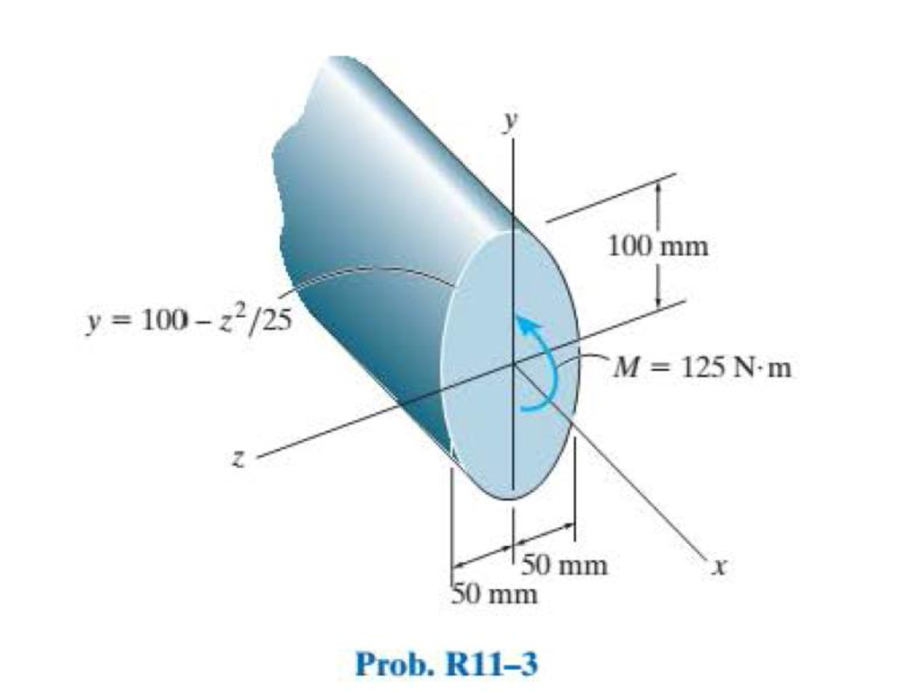
Chapter 11, Problem 3RP
A shaft is made of a polymer having a parabolic upper and lower cross section. If it resists a moment of M = 125 N·m, determine the maximum bending stress in the material (a) using the flexure formula and (b) using integration. Sketch a three-dimensional view of the stress distribution acting over the cross-sectional area. Hint: The moment of inertia is determined using Eq. A–3 of Appendix A.
Expert Solution & Answer
Want to see the full answer?
Check out a sample textbook solution
Students have asked these similar questions
Determine the torsional shear stress in the shaft section AB and BC. There is a fixed support at
C that can resist a moment. (Image taken from Statics and Mechanics of Materials by Beer, Johnson, DeWolf and Mazurek)
T₁ = 300 N-m
30 mm
TB = 400 N-m
46 mm
055
Shear Stress in AB =
Shear Stress in BC=
B
0.9 m
0.75 m
units:
units:
The aluminium machine part shown below is subjected to a moment of M
= 75 N.m. Determine the bending stress created at points B and A on the
cross section. Sketch the results on a volume element located at each of
these points.
A-
50mm
50mm
100mm
100mm
20mm
B-
M=8kN-m
20mm
Below Figure shows the section of an angle purlin. A bending moment of
5 kN.m is applied to the purlin in a plane at an angle of 30 deg to the
vertical y axis. If the sense of the bending moment is such that both its
components Mx and My produce tension in the positive xy quadrant,
calculate the maximum direct stress in the purlin, stating clearly the point
at which it acts. *
100 mm
E
10mm
30
C D
-10mm
57 MPa.
89 MPa.
Non Above
O 72 MPa.
125mm
Chapter 11 Solutions
EBK STATICS AND MECHANICS OF MATERIALS
Ch. 11.2 - In each case, the beam is subjected to the...Ch. 11.2 - In each ease, express the shear and moment...Ch. 11.2 - In each ease, express the shear and moment...Ch. 11.2 - In each ease, express the shear and moment...Ch. 11.2 - In each ease, express the shear and moment...Ch. 11.2 - Prob. 5FPCh. 11.2 - Prob. 6FPCh. 11.2 - In each ease, draw the shear and moment diagrams...Ch. 11.2 - Prob. 8FPCh. 11.2 - Prob. 1P
Ch. 11.2 - Draw the shear and moment diagrams for the beam,...Ch. 11.2 - Draw the shear and moment diagrams for the beam,...Ch. 11.2 - Express the shear and moment in terms of x for 0 ...Ch. 11.2 - Express the internal shear and moment in the...Ch. 11.2 - Prob. 6PCh. 11.2 - Express the internal shear and moment in terms of...Ch. 11.2 - Draw the shear and moment diagrams for the beam,...Ch. 11.2 - If the force applied to the handle of the load...Ch. 11.2 - Draw the shear and moment diagrams for the shaft....Ch. 11.2 - The crane is used to support the engine, which has...Ch. 11.2 - Prob. 12PCh. 11.2 - Draw the shear and moment diagrams for the beam....Ch. 11.2 - Draw the shear and moment diagrams for the beam....Ch. 11.2 - Members ABC and BD of the counter chair are...Ch. 11.2 - A reinforced concrete pier is used to support the...Ch. 11.2 - Draw the shear and moment diagrams for the beam...Ch. 11.2 - The industrial robot is held in the stationary...Ch. 11.2 - Determine the placement distance a of the roller...Ch. 11.2 - Prob. 20PCh. 11.2 - Draw the shear and moment diagrams for the beam....Ch. 11.2 - Draw the shear and moment diagrams for the...Ch. 11.2 - The 150-lb man sits in the center of the boat,...Ch. 11.2 - Prob. 24PCh. 11.2 - The footing supports the load transmitted by the...Ch. 11.2 - Prob. 26PCh. 11.2 - Prob. 27PCh. 11.2 - Draw the shear and moment diagrams for the beam....Ch. 11.2 - Draw the shear and moment diagrams for the beam....Ch. 11.2 - Prob. 30PCh. 11.2 - Prob. 31PCh. 11.2 - Prob. 32PCh. 11.2 - The shaft is supported by a smooth thrust bearing...Ch. 11.2 - Draw the shear and moment diagrams for the...Ch. 11.2 - Draw the shear and moment diagrams for the beam....Ch. 11.2 - Draw the shear and moment diagrams for the rod....Ch. 11.2 - Draw the shear and moment diagrams for the beam....Ch. 11.2 - Prob. 38PCh. 11.2 - Draw the shear and moment diagrams for the double...Ch. 11.2 - Draw the shear and moment diagrams for the simply...Ch. 11.2 - The compound beam is fixed at A, pin connected at...Ch. 11.2 - Draw the shear and moment diagrams for the...Ch. 11.2 - The compound beam is fixed at A, pin connected at...Ch. 11.2 - Draw the shear and moment diagrams for the beam....Ch. 11.2 - A short link at B is used to connect beams AB and...Ch. 11.2 - The truck is to be used to transport the concrete...Ch. 11.4 - Determine the moment of inertia of the cross...Ch. 11.4 - Prob. 3PPCh. 11.4 - In each case, show how the bending stress acts on...Ch. 11.4 - Prob. 5PPCh. 11.4 - If the beam is subjected to a bending moment of M...Ch. 11.4 - If the beam is subjected to a bending moment of M...Ch. 11.4 - If the beam is subjected to a bending moment of M...Ch. 11.4 - Prob. 12FPCh. 11.4 - If the beam is subjected to a bending moment of M...Ch. 11.4 - An A-36 steel strip has an allowable bending...Ch. 11.4 - Determine the moment M that will produce a maximum...Ch. 11.4 - Determine the maximum tensile and compressive...Ch. 11.4 - The beam is constructed from four pieces of wood,...Ch. 11.4 - The beam is constructed from four pieces of wood,...Ch. 11.4 - The beam is made from three boards nailed together...Ch. 11.4 - Prob. 53PCh. 11.4 - If the built-up beam is subjected to an internal...Ch. 11.4 - If the built-up beam is subjected to an internal...Ch. 11.4 - Prob. 56PCh. 11.4 - Determine the moment M that should be applied to...Ch. 11.4 - Prob. 58PCh. 11.4 - Prob. 59PCh. 11.4 - The beam is subjected to a moment of 15 kip ft....Ch. 11.4 - The beam is subjected to a moment of 15 kip ft....Ch. 11.4 - Prob. 62PCh. 11.4 - The steel shaft has a diameter of 2 in. It is...Ch. 11.4 - The beam is made of steel that has an allowable...Ch. 11.4 - Prob. 65PCh. 11.4 - Solve Prob. 11-65 if the moment M = 50 N m is...Ch. 11.4 - The shaft is supported by smooth journal bearings...Ch. 11.4 - Prob. 68PCh. 11.4 - Prob. 69PCh. 11.4 - The strut on the utility pole supports the cable...Ch. 11.4 - Prob. 71PCh. 11.4 - Prob. 72PCh. 11.4 - Determine the smallest allowable diameter of the...Ch. 11.4 - Prob. 74PCh. 11.4 - The shaft is supported by a thrust bearing at A...Ch. 11.4 - If the intensity of the load w = 15 kN/m,...Ch. 11.4 - If the allowable bending stress is allow = 150...Ch. 11.4 - The beam is subjected to the triangular...Ch. 11.4 - The beam has a rectangular cross section with b =...Ch. 11.4 - Determine the absolute maximum bending stress in...Ch. 11.4 - If the compound beam in Prob. 11-42 has a square...Ch. 11.4 - Prob. 82PCh. 11.4 - Prob. 83PCh. 11.4 - Determine, to the nearest millimeter, the smallest...Ch. 11.4 - Prob. 85PCh. 11.4 - Determine the absolute maximum bending stress in...Ch. 11.4 - Determine the smallest diameter of the shaft to...Ch. 11.4 - Prob. 88PCh. 11.4 - A log that is 2 ft in diameter is to be cut into a...Ch. 11.4 - The simply supported truss is subjected to the...Ch. 11.4 - Prob. 92PCh. 11.4 - Prob. 93PCh. 11.4 - Prob. 94PCh. 11.4 - The beam has the rectangular cross section shown....Ch. 11.5 - Determine the bending stress developed at corners...Ch. 11.5 - Prob. 15FPCh. 11.5 - Prob. 96PCh. 11.5 - Prob. 97PCh. 11.5 - Prob. 98PCh. 11.5 - Prob. 99PCh. 11.5 - Determine the bending stress at point A of the...Ch. 11.5 - The steel shaft is subjected to the two loads. If...Ch. 11.5 - Prob. 102PCh. 11.5 - Prob. 103PCh. 11.5 - Prob. 104PCh. 11 - Determine the shape factor for the wide-flange...Ch. 11 - The compound beam consists of two segments that...Ch. 11 - A shaft is made of a polymer having a parabolic...Ch. 11 - Determine the maximum bending stress in the handle...Ch. 11 - Determine the shear and moment in the beam as...Ch. 11 - A wooden beam has a square cross section as shown....Ch. 11 - Prob. 7RPCh. 11 - The strut has a square cross section a by a and is...
Knowledge Booster


Learn more about
Need a deep-dive on the concept behind this application? Look no further. Learn more about this topic, mechanical-engineering and related others by exploring similar questions and additional content below.Similar questions
- Below Figure shows the section of an angle purlin. A bending moment of 60 5 kN.m is applied to the purlin in a plane at an angle of 30 deg to the vertical y axis. If the sense of the bending moment is such that both its components Mx and My produce tension in the positive xy quadrant, calculate the maximum direct stress in the purlin, stating clearly the point at which it acts. * 100 mm BỊ 10mm 30° C ID 10mm 57 MPa. 89 MPa. Non Above 72 MPa. 125mmarrow_forwardcalculate the maximum bending stress when the shaft is rotating at 80% of the critical speedarrow_forwardFind the shear force and bending moment at points B and D. Note: B lies just to the right of the 150 lbf force and D is just to the right of the bearing at C. The bearing at A is a thrust bearing, while the bearing at C is a journal bearing. 150 lb A Answer: VB = -100 lbf MB = 750 lbf in VD = 75lbf Mp = -750 lbf in I 15 in. B 15 in. C. D 75 lb 10 in.arrow_forward
- The axle of the freight train is subjected to loadings as shown below. The diameter of the axle is 137.5 mm. If it is supported by two journal bearings at C and D, determine the maximum bending stress. Include a FBD, SFD and BMD using either the section or graphical method. Draw a cross-section of the shaft and indicate the points of maximum tension and compression. A B 250 mm 100 kN 1500 mm- Answer 0= +98 MPa 250 mm 100 kNarrow_forwardConsider that the section is transmitting a positive bending moment about the z axis,Mz, where Mz=10 kip*in if the dimensions of the section are given in ips units, or Mz=1.13kN*m if the dimensions are in SI units. Determine the resulting stresses at the top and bottom surfaces and at every abrupt change in the cross section. Find the second moment of area, the location of the neutral axis, and the distances from the neutral axis to the top and bottom surfaces.arrow_forwardDetermine the moment M that should be applied to the beam in order to create a compressive stress at point D of σD = 30 MPa. Also sketch the stress distribution acting over the cross section and calculate the maximum stress in the beam. Construct the stress distribution in 2D similar to in-class examples, rather than isometrically similar to the textbook examples for clarity. Hint: The maximum stress will occur at the extreme fiber (Either top or bottom). For symmetric cross- sections, the extreme fiber for the tensile and compressive stresses will have the same magnitude. A 25 mm M D 150 mm 25 mm 25 mm B 150 mm 25 mmarrow_forward
- Find the second moment of area, the location of the neutral axis, and the distances from the neutral axis to the top and bottom surfaces. Consider that the section is transmitting a positive bending moment about the z axis, Mz, where M₂ = 10 kip-in if the dimensions of the section are given in ips units, or M₂ = 1.13 kN·m if the dimensions are in Sl units. Determine the resulting stresses at the top and bottom surfaces and at every abrupt change in the cross section. From the figure, с - 12.5 B A y I 50 100 75 12.5- 12.5 25 D 100 The area is determined to be 3750 mm² The distances from the neutral axis to the top and bottom surfaces are determined to be 57.292 The second moment of area is determined to be 4.293 x 106 mm4. mm and 42.708 ✪ mm.arrow_forwardFind the second moment of area, the location of the neutral axis, and the distances from the neutral axis to the top and bottom surfaces. Consider that the section is transmitting a positive bending moment about the z axis, Mz, where M₂ = 10 kip-in if the dimensions of the section are given in ips units, or M₂ = 1.13 kN·m if the dimensions are in Sl units. Determine the resulting stresses at the top and bottom surfaces and at every abrupt change in the cross section. From the figure Z 1 in 112 in y in → ← ¹ in 12 in D C B A ++ in The area is determined to be 2.0625 in². The distances from the neutral axis to the top and bottom surfaces are determined to be 0.858 x in and The second moment of area is determined to be 0.447 in 4. 1.017 xin.arrow_forwardThe axle of the freight train is subjected to loadings as shown below. The diameter of the axle is 137.5 mm. If it is supported by two journal bearings at C and D, determine the maximum bending Stress. Include a FBD, SFD and BMD using either the section or graphical method. Draw a cross-section of the shaft and indicate the points of maximum tension and compression.arrow_forward
- The rod shown below is of diamater 70 mm and is fixed at one end. It is subjected to 500 N.m and 300 N.m torsional moments as shown. Sketch the distribution of the internal torsional moment along the length of the rod. Also find the torsional shear stress at points A and B, and also the largest shear stress in the rod. Point B is to the left of the 500 N.m torsional moment and A is on the right of it. Round-up your answers to the nearest 1/100th of an MPa. y 35 mm 20 mm 500 N.m 35 mm- 300 N.m Torsional shear stress at A = MPа %3D Torsional shear stress at B = MPа Maximum shear stress = MPa %3Darrow_forwardA shaft with a length of 2 m has the cross section shown in Figure 1, where a = 4 cm and t = 4 mm. Calculate the torsional bending constant Γ of the shaft. If only one end is allowed to warp, calculate the relative angle of rotation between the two ends of the shaft with a torque of 200 Nm. Assuming the material is isotropic, E = 200 Gpa, υ = 0.3.arrow_forward3 m 3 m A B D When the CD temperature rises by 60 ° C, calculate the internal force of the column with a diameter of 75mm. At the beginning, there is no gap between the column and the beam, and the beam is in light contact. The column is made of A-36 steel, and the moment of inertia of the beam is i=255 (10^6) mm^4 C 3 marrow_forward
arrow_back_ios
SEE MORE QUESTIONS
arrow_forward_ios
Recommended textbooks for you
 Mechanics of Materials (MindTap Course List)Mechanical EngineeringISBN:9781337093347Author:Barry J. Goodno, James M. GerePublisher:Cengage Learning
Mechanics of Materials (MindTap Course List)
Mechanical Engineering
ISBN:9781337093347
Author:Barry J. Goodno, James M. Gere
Publisher:Cengage Learning
Everything About COMBINED LOADING in 10 Minutes! Mechanics of Materials; Author: Less Boring Lectures;https://www.youtube.com/watch?v=N-PlI900hSg;License: Standard youtube license