
STANDALONE CODE MECHANICS OF MATERIALS-M
11th Edition
ISBN: 9780137605200
Author: HIBBELER
Publisher: PEARSON
expand_more
expand_more
format_list_bulleted
Videos
Textbook Question
Chapter 11, Problem 8RP
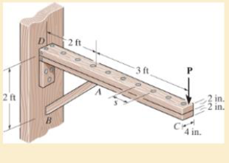
by 4-in. pieces of wood braced as shown. If the allowable bending stress is σallow = 600 psi, determine the largest load P that can be applied. Also, determine the maximum spacing of nails, s, along the beam section AC if each nail can resist a shear force of 800 lb. Assume the beam is pin connected at A, B, and D. Neglect the axial force developed in the beam along DA.
Expert Solution & Answer
Want to see the full answer?
Check out a sample textbook solution
Students have asked these similar questions
The simply supported joist is used in the construction of a floor for a building. In order to keep the floor low with respect to the sill beams C and D, the ends of the joists are notched as shown. If the allowable shear stress is tallow = 350 psi and the allowable bending stress is sallow = 1500 psi, determine the height h that will cause the beam to reach both allowable stresses at the same time. Also, what load P causes this to happen? Neglect the stressconcentration at the notch.
The axle of the freight train is subjected to loadings as shown below. The diameter of the axle is 137.5 mm.
If it is supported by two journal bearings at C and D, determine the maximum bending Stress. Include a FBD, SFD and BMD using either the section or graphical method. Draw a cross-section of the shaft and indicate the points of maximum tension and compression.
A 20 ft long simply supported beam has 15-inch outside diameter with 1-inch-thick circular section. The beam carries 10 lb/ft uniformly distributed load from the right support to its middle span. Another 15 lb concentrated load applied downward in the left-end support. Determine the maximum bending stress (k-lb/ft2) of the simply supported beam.
Chapter 11 Solutions
STANDALONE CODE MECHANICS OF MATERIALS-M
Ch. 11.2 - Determine the minimum dimension a to the nearest...Ch. 11.2 - of the rod to safely support the load. The rod is...Ch. 11.2 - The wood has an allowable normal stress of allow =...Ch. 11.2 - of the beam's cross section to safely support the...Ch. 11.2 - Determine the minimum dimension b to the nearest...Ch. 11.2 - The beam is made of steel having an allowable...Ch. 11.2 - Determine the minimum width of the beam to the...Ch. 11.2 - if P=10 kip.Ch. 11.2 - The beam has an allowable normal stress of allow...Ch. 11.2 - If each beam is to be designed to carry 90 lb/ft...
Ch. 11.2 - Determine its height h so that it simultaneously...Ch. 11.2 - to safely support the load. The wood has an...Ch. 11.2 - and the wood has an allowable normal stress of...Ch. 11.2 - if allow = 30 ksi and allow = 15 ksi. The journal...Ch. 11.2 - if allow = 30 ksi and allow = 15 ksi. The journal...Ch. 11.2 - The tapered beam supports a uniform distributed...Ch. 11.2 - Determine the variation in the depth d of a...Ch. 11.2 - Prob. 41PCh. 11.2 - The pulleys fixed to the shaft are loaded as...Ch. 11.2 - Prob. 43PCh. 11.2 - Prob. 44PCh. 11 - The cantilevered beam has a circular cross...Ch. 11 - Select the lightest-weight wide-flange overhanging...Ch. 11 - Prob. 3RPCh. 11 - Determine the shaft's diameter to the nearest...Ch. 11 - Select the lightest-weight wide-flange beam from...Ch. 11 - The simply supported joist is used in the...Ch. 11 - The simply supported joist is used in the...Ch. 11 - by 4-in. pieces of wood braced as shown. If the...
Additional Engineering Textbook Solutions
Find more solutions based on key concepts
Determine the velocity of block D if end A of the rope is pulled down with a speed of vA = 3 m/s.
Engineering Mechanics: Dynamics (14th Edition)
Find the change in length of side AB.
Mechanics of Materials, 7th Edition
A 20-lb force is applied to the control rod AB as shown. Knowing that the length of the rod is 9 in. and that t...
Statics and Mechanics of Materials
The triple jump is a track-and-field event in which an athlete gets a running start and tries to leap as far as...
Vector Mechanics For Engineers
19.8 Calculate the allowable tensile load for the connection shown. The plates are ASTM A36 steel and the weld ...
Applied Statics and Strength of Materials (6th Edition)
A number of common substances are
Some of these materials exhibit characteristics of both solid and fluid beha...
Fox and McDonald's Introduction to Fluid Mechanics
Knowledge Booster


Learn more about
Need a deep-dive on the concept behind this application? Look no further. Learn more about this topic, mechanical-engineering and related others by exploring similar questions and additional content below.Similar questions
- The simply supported joist is used in the construction of a floor for a building. In order to keep the floor low with respect to the sill beams C and D, the ends of the joist are notched as shown. If the allowable shear stress is tallow = 350 psi and the allowable bending stress is s allow = 1700 psi, determine the smallest height h so that the beam will support a load of P = 600 lb. Also, will the entire joist safely support the load? Neglect the stress concentration at the notch.arrow_forwardIf the simply supported beam is subjected to the load shown below, determine the following: c- c - The internal bending moment acting on the cross-section through point C. d- d- The shear stress at section C.arrow_forwardThe box beam is made by nailing four 2-in. by 8-in. plankstogether as shown. Given that w0 = 300 lb/ft, find the largestallowable force P if the bending stress is limited to 1400 psi.arrow_forward
- Determine the resultant internal loadings acting on the cross section at B of the pipe shown. End A is subjected to a vertical force P and a horizontal force Q. Use P = 90 N and Q = 70 N. a. Determine the internal axial force (in N) in section B. b. Determine the internal shear force (in N) in section B. c. Determine the internal torque (in N-m) in section B. With FBD please thank you.arrow_forwardFor the beam in question 1, determine the maximum bending and shear stressesat point C, at point P of the section. Represent the stress cube.arrow_forwardThe axle of the freight train is subjected to loadings as shown below. The diameter of the axle is 137.5 mm. If it is supported by two journal bearings at C and D, determine the maximum bending stress. Include a FBD, SFD and BMD using either the section or graphical method. Draw a cross-section of the shaft and indicate the points of maximum tension and compression. A B 250 mm 100 kN 1500 mm- Answer 0= +98 MPa 250 mm 100 kNarrow_forward
- If M = 1 kip # ft, determine the resultant force the bending stresses produce on the top board A of the beam.arrow_forwardThe eye hook has the dimensions shown. If it supports a cable loading of 800 lb, determine the maximum normal stress at section a–a and sketch the stress distribution acting over the cross section. Use the curved-beam formula to calculate the bending stress.arrow_forwardDetermine the ff: •Internal bending moment at point c •internal shear force at point c •internal normal force at point c Asap please.arrow_forward
- Smooth journal bearings at A and B that only exert vertical reactions on the shaft as shown below support the shaft. Based on the loading and support conditions shown, address the following: (a) Sketch the shear and moment diagrams using the graphical method - label all significant conditions. (b) If d = 90 mm, determine the absolute maximum bending stress in the beam, and sketch the stress distribution acting over the cross section. A 3 m 12 kN/m B 1.5 marrow_forwardThe 40-mm diameter solid shaft ACBD is supported by two bearings at A and B. Due to the transmission of power to and from the shaft, the belts of the pulleys are subjected to the tension forces shown in the figure below. 1-Draw the moment and shear diagrams on the y z and y x planes 2-Determine the location and magnitude of the maximum bending (normal) stress. Hint draw the shaft cross section at that location and think of the associated stresses. 0.050 m 300 N 0.250 m 200 N 550 N 0.250 m 400 N 150m D 0.075 marrow_forward1. For the simply supported beam with a T-shape cross-section as shown below, a- Draw the shear and moments diagram of the beam. b- Determine the maximum normal bending stress and specify its location. C- If the beam made from two boards determines the maximum shear stress in the glue necessary to hold the boards together along the seam where they are joined. d- Determine the shear stress at point B. 4 m 6.5 kN/m 6m- Glue 150 mm 30 mm 150 mm 30 mmarrow_forward
arrow_back_ios
SEE MORE QUESTIONS
arrow_forward_ios
Recommended textbooks for you
 Elements Of ElectromagneticsMechanical EngineeringISBN:9780190698614Author:Sadiku, Matthew N. O.Publisher:Oxford University Press
 Mechanics of Materials (10th Edition)Mechanical EngineeringISBN:9780134319650Author:Russell C. HibbelerPublisher:PEARSON
 Thermodynamics: An Engineering ApproachMechanical EngineeringISBN:9781259822674Author:Yunus A. Cengel Dr., Michael A. BolesPublisher:McGraw-Hill Education
 Control Systems EngineeringMechanical EngineeringISBN:9781118170519Author:Norman S. NisePublisher:WILEY
 Mechanics of Materials (MindTap Course List)Mechanical EngineeringISBN:9781337093347Author:Barry J. Goodno, James M. GerePublisher:Cengage Learning
 Engineering Mechanics: StaticsMechanical EngineeringISBN:9781118807330Author:James L. Meriam, L. G. Kraige, J. N. BoltonPublisher:WILEY
Elements Of Electromagnetics
Mechanical Engineering
ISBN:9780190698614
Author:Sadiku, Matthew N. O.
Publisher:Oxford University Press
Mechanics of Materials (10th Edition)
Mechanical Engineering
ISBN:9780134319650
Author:Russell C. Hibbeler
Publisher:PEARSON
Thermodynamics: An Engineering Approach
Mechanical Engineering
ISBN:9781259822674
Author:Yunus A. Cengel Dr., Michael A. Boles
Publisher:McGraw-Hill Education
Control Systems Engineering
Mechanical Engineering
ISBN:9781118170519
Author:Norman S. Nise
Publisher:WILEY
Mechanics of Materials (MindTap Course List)
Mechanical Engineering
ISBN:9781337093347
Author:Barry J. Goodno, James M. Gere
Publisher:Cengage Learning
Engineering Mechanics: Statics
Mechanical Engineering
ISBN:9781118807330
Author:James L. Meriam, L. G. Kraige, J. N. Bolton
Publisher:WILEY
Mechanics of Materials Lecture: Beam Design; Author: UWMC Engineering;https://www.youtube.com/watch?v=-wVs5pvQPm4;License: Standard Youtube License