
Videos
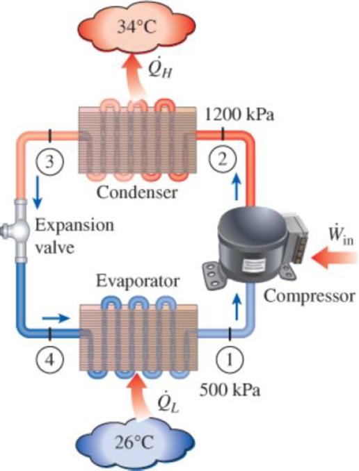
An air conditioner with refrigerant-134a as the working fluid is used to keep a room at 26°C by rejecting the waste heat to the outside air at 34°C. The room is gaining heat through the walls and the windows at a rate of 250 kJ/min while the heat generated by the computer, TV, and lights amounts to 900 W. An unknown amount of heat is also generated by the people in the room. The condenser and evaporator pressures are 1200 and 500 kPa, respectively. The refrigerant is saturated liquid at the condenser exit and saturated vapor at the compressor inlet. If the refrigerant enters the compressor at a rate of 100 L/min and the isentropic efficiency of the compressor is 75 percent, determine (a) the temperature of the refrigerant at the compressor exit, (b) the rate of heat generation by the people in the room, (c) the COP of the air conditioner, and (d) the minimum volume flow rate of the refrigerant at the compressor inlet for the same compressor inlet and exit conditions.
FIGURE P11–115
(a)
The temperature of the refrigerant at the compressor exit.
Answer to Problem 115RP
The temperature of the refrigerant at the compressor exit is
Explanation of Solution
Show the T-s diagram as in Figure (1).
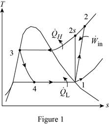
From Figure (1), write the specific enthalpy at state 3 is equal to state 4 due to throttling process.
Here, specific enthalpy at state 3 and 4 is
Express the specific enthalpy at state 2.
Here, specific enthalpy at state 2s is
Conclusion:
Perform the unit conversion of pressure at state 1 from
Refer Table A-13, “superheated refrigerant-134a”, and write the properties corresponding to pressure of
Here, specific enthalpy, volume and entropy is
Perform the unit conversion of pressure at state 2 from
Refer Table A-12, “saturated refrigerant-134a-pressure table”, and write the specific enthalpy at state 3 corresponding to pressure at state 3 of
Here, specific enthalpy at saturated liquid is
Substitute
Refer Table A-13, “superheated refrigerant 134a”, and write the specific enthalpy at state 2s corresponding to pressure at state 2 of
Write the formula of interpolation method of two variables.
Here, the variables denote by x and y is specific entropy at state 2 and specific enthalpy at state 2 respectively.
Show the specific enthalpy at state 2s corresponding to specific entropy as in Table (1).
|
Specific entropy at state 2 |
Specific enthalpy at state 2s |
| 0.9132 | 273.92 |
| 0.9242 | |
| 0.9268 | 278.28 |
Substitute
Thus, the specific enthalpy at state 2s is,
Substitute
Refer Table A-13, “superheated refrigerant 134a”, and write the temperature at state 2 corresponding to pressure at state 2 of
Show the temperature at state 2 corresponding to specific enthalpy at state 2 as in Table (2).
|
Specific enthalpy at state 2s |
Temperature at state 2 |
| 278.28 | 50 |
| 283.48 | |
| 289.66 | 60 |
Use excels and tabulates the values form Table (2) in Equation (III) to get,
Hence, the temperature of the refrigerant at the compressor exit is
(b)
The rate of heat generation by the people in the room.
Answer to Problem 115RP
The rate of heat generation by the people in the room is
Explanation of Solution
Express the mass flow rate of the refrigerant.
Here, volume flow rate at state 1 is
Express the refrigeration load.
Express the rate of heat generation by the people in the room.
Here, rate of heat generated is
Conclusion:
Substitute
Substitute
Substitute
Hence, the rate of heat generation by the people in the room is
(c)
The COP of the air conditioner.
Answer to Problem 115RP
The COP of the air conditioner is
Explanation of Solution
Express the rate of work input.
Express the coefficient of performance of the air conditioner.
Conclusion:
Substitute
Substitute
Hence, the COP of the air conditioner is
(d)
The minimum volume flow rate of the refrigerant at the compressor inlet.
Answer to Problem 115RP
The minimum volume flow rate of the refrigerant at the compressor inlet is
Explanation of Solution
Express the reversible coefficient of performance of the cycle.
Here, high and low temperature medium is
Express corresponding minimum power input.
Express the minimum mass flow rate.
Express the minimum volume flow rate of the refrigerant at the compressor inlet
Conclusion:
Substitute
Substitute
Substitute
Substitute
Hence, the minimum volume flow rate of the refrigerant at the compressor inlet is
Want to see more full solutions like this?
Chapter 11 Solutions
Thermodynamics: An Engineering Approach


- A commercial refrigerator with refrigerant-134a as the working fluid is used to keep the refrigerated space at –35°C by rejecting waste heat to cooling water that enters the condenser at 18°C at a rate of 0.25 kg/s and leaves at 26°C. The refrigerant enters the condenser at 1.2 MPa and 50°C and leaves at the same pressure subcooled by 5°C. If the compressor consumes 3.3 kW of power, determine the refrigeration load.arrow_forwardA commercial refrigerator with refrigerant-134a as the working fluid is used to keep the refrigerated space at –35°C by rejecting waste heat to cooling water that enters the condenser at 18°C at a rate of 0.25 kg/s and leaves at 26°C. The refrigerant enters the condenser at 1.2 MPa and 50°C and leaves at the same pressure subcooled by 5°C. If the compressor consumes 3.3 kW of power, determine the minimum power input to the compressor for the same refrigeration load.arrow_forwardA commercial refrigerator with refrigerant-134a as the working fluid is used to keep the refrigerated space at -35°C by rejecting waste heat to cooling water that enters the condenser at 18°C at a rate of 0.25 kg/s and leaves at 26°C. The refrigerant enters the condenser at 1.2 MPa and 50°C and leaves at the same pressure subcooled by 5°C. If the compressor consumes 3.3 kW of power, determine (a) the mass flow rate of the refrigerant, (b) the refrigeration load, (c) the COP, and (d) the minimum power input to the compressor for the same refrigeration load.arrow_forward
- Consider a refrigeration system using refrigerant-134a as the working fluid. If this refrigerator is to operate in an environment at 20°C, what is the minimum pressure to which the refrigerant should be compressed? Why?arrow_forwardA commercial refrigerator with refrigerant-134a as the working fluid is used to keep the refrigerated space at –30°C by rejecting its waste heat to cooling water that enters the condenser at 18°C at a rate of 0.25 kg/s and leaves at 26°C. The refrigerant enters the condenser at 1.2 MPa and 65°C and leaves at 42°C. The inlet state of the compressor is 60 kPa and –34°C and the compressor is estimated to gain a net heat of 450 W from the surroundings. Determine the theoretical maximum refrigeration load for the same power input to the compressor. Water 26°C ↑ 18°C 1.2 MPа 42°C 65°C Condenser Expansion Win valve Evaporator Compressor 60 kPa -34°Carrow_forwardA refrigerator uses R-134a as the working fluid and operates on an ideal vapor compression cycle between 0.14 MPa and 0.8 MPa. If the mass flow rate of the refrigerant is 0.06 kg/s, determine (a) the rate of heat removal from the refrigerated space, (b) the power input to the compressor, (c) the heat rejection rate in the condenser, and (d) the COP.arrow_forward
- A Carnot refrigeration cycle is executed in a closed system in the saturated liquid-vapor mixture region using 1 kg of refrigerant-134a as the working fluid. The maximum and the minimum temperatures in the cycle are 22C and -4C, respectively. If the refrigerant is saturated liquid at the end of the heat rejection process, and the net work input to the cycle is 16 kJ, determine: b) The pressure at the end of the heat rejection process. Should correct please. (Gpt/ai Answer not allowed)arrow_forwardConsider a Carnot heat-engine cycle executed in a closed system using 0.01 kg of refrigerant-134a as the working fluid. The cycle has a thermal efficiency of 15 percent, and therefrigerant-134a changes from saturated liquid to saturated vapor at 50°C during the heat addition process. Determine the net work output of this engine per cycle.arrow_forwardA refrigerated room is kept at −18◦C by a vapor-compression cycle with R-134a as the refrigerant. Heat is rejected to cooling water that enters the condenser at 14◦C at a rate of 0.35 kg/s and leaves at 22◦C. The refrigerant enters the condenser at 1.2MPa and 50◦C and leaves at the same pressure subcooled by 5◦C. If the compressor consumes 5.5 kW of power, determine (a) the mass flow rate of the refrigerant, (b) the refrigeration load and the COP, (c) the second-law efficiency of the refrigerator and the total exergy destruction in the cycle, and (d) the exergy destruction in the condenser. Take specific heat of water to be 4.18 kJ/kg·◦C.arrow_forward
- Refrigerant-134a enters the compressor of a refrigerator at 0.14MPa and -10°C at a rate of 0.05 kg/s and leaves at 0.8 MPa and 50°C. The refrigerant is cooled in the condenser to 26°C and 0.72 MPa and is throttled to 0.15 MPa. Determine (a) the rate of heat removal from the refrigerated space and the power input to the compressor, (b) the isentropic efficiency of the compressor, and (c) the coefficient of performance of the refrigerator. Answers: (a) 7.93 kW, 2.02 kW, (b) 0.939, (c) 3.93arrow_forwardConsider a refrigrator that operates on the vapor compression refrigeration cycle with R-134a as the working fluid. The refrigerant enters the compressor as saturated vapor at 70 kPa, and exits at 1200 kPa and 90°C, and leaves the condenser as saturated liquid at 1200 kPa. The coefficient of performance of this refrigrator isarrow_forwardA commercial refrigerator using R-134a as a refrigerant is used to keep the cooled environment at -35 C. The refrigerator releases the waste heat to the cooling water that enters the condenser at 18 C at 0.25 kg / s and leaves the condenser at 26 C. The refrigerant enters the condenser at a pressure of 1.2 MPa and a temperature of 50 ° C, and leaves the condenser at the same pressure, supercooled at 5 ° C. Since the compressor consumes 3.3 kW of power, a) Mass flow rate of the refrigerant, b) Cooling load and COP value c) Calculate the minimum power consumed by the compressor for the same cooling load.arrow_forward
 Elements Of ElectromagneticsMechanical EngineeringISBN:9780190698614Author:Sadiku, Matthew N. O.Publisher:Oxford University Press
 Mechanics of Materials (10th Edition)Mechanical EngineeringISBN:9780134319650Author:Russell C. HibbelerPublisher:PEARSON
 Thermodynamics: An Engineering ApproachMechanical EngineeringISBN:9781259822674Author:Yunus A. Cengel Dr., Michael A. BolesPublisher:McGraw-Hill Education
 Control Systems EngineeringMechanical EngineeringISBN:9781118170519Author:Norman S. NisePublisher:WILEY
 Mechanics of Materials (MindTap Course List)Mechanical EngineeringISBN:9781337093347Author:Barry J. Goodno, James M. GerePublisher:Cengage Learning
 Engineering Mechanics: StaticsMechanical EngineeringISBN:9781118807330Author:James L. Meriam, L. G. Kraige, J. N. BoltonPublisher:WILEY