
Videos
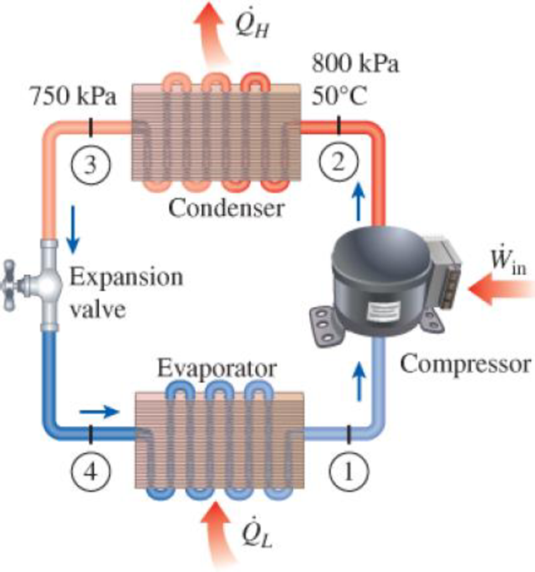
Refrigerant-134a enters the condenser of a residential heat pump at 800 kPa and 50°C at a rate of 0.022 kg/s and leaves at 750 kPa subcooled by 3°C. The refrigerant enters the compressor at 200 kPa superheated by 4°C. Determine (a) the isentropic efficiency of the compressor, (b) the rate of heat supplied to the heated room, and (c) the COP of the heat pump. Also, determine (d) the COP and the rate of heat supplied to the heated room if this heat pump operated on the ideal vapor-compression cycle between the pressure limits of 200 and 800 kPa.
FIGURE P11–42
(a)
The isentropic efficiency of the compressor.
Answer to Problem 42P
The isentropic efficiency of the compressor is
Explanation of Solution
Show the T-s diagram for process as in Figure (1).
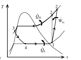
From Figure (1), write the specific enthalpy at state 3 is equal to state 4 due to throttling process.
Here, specific enthalpy at state 3 and 4 is
Express isentropic efficiency of the compressor.
Here, specific enthalpy at state 1, 2 and 2s is
Express the temperature at state 3.
Here, saturated temperature at pressure of
Express the temperature at state 1.
Here, saturated temperature at pressure of
Express quality at state 2s.
Here, specific entropy at saturated liquid and evaporation and
Express specific enthalpy at state 2s.
Here, specific enthalpy at saturated liquid and evaporation and
Conclusion:
Perform unit conversion of pressure at state 2 from
Refer Table A-13, “superheated refrigerant 134a”, and write the specific enthalpy at state 2 corresponding to pressure at state 2 of
Refer Table A-12, “saturated refrigerant-134a-pressure table” and write saturated temperature at pressure of
Substitute
Refer Table A-12, “saturated refrigerant-134a-pressure table” and write specific enthalpy at state 3 corresponding to pressure at state 3 of
Write the formula of interpolation method of two variables.
Here, the variables denote by x and y is temperature at state 3 and specific enthalpy at state 3 respectively.
Show the specific enthalpy at state 3 corresponding to temperature as in Table (1).
|
Temperature at state 3 |
Specific enthalpy at state 3 |
| 26.69 | 88.82 |
| 26.06 | |
| 29.06 | 92.22 |
Substitute
Since the specific enthalpy at state 3 is equal to state 4 due to throttling process.
Refer Table A-12, “saturated refrigerant-134a-pressure table” and write saturated temperature at pressure of
Substitute
Refer Table A-12, “saturated refrigerant-134a-pressure table” and write specific enthalpy and entropy at state 1 corresponding to pressure at state 1 of
Here, specific entropy at state 1 is
The specific entropy at state 1 is equal to specific entropy at state 1.
Here, specific entropy at state 2 is
Refer Table A-12, “saturated refrigerant-134a-pressure table” and write the properties corresponding to pressure at state 2 of
Substitute
Substitute
Substitute
Hence, the isentropic efficiency of the compressor is
(b)
The rate of heat supplied to the heated room.
Answer to Problem 42P
The rate of heat supplied to the heated room is
Explanation of Solution
Express the rate of heat supplied to the heated room.
Here, mass flow rate is
Conclusion:
Substitute
Hence, the rate of heat supplied to the heated room is
(c)
The COP of the heat pump.
Answer to Problem 42P
The COP of the heat pump is
Explanation of Solution
Express the rate of work input.
Express coefficient of performance of heat pump.
Conclusion:
Substitute
Substitute
Hence, the COP of the heat pump is
(d)
The COP and the rate of heat supplied to the heated room.
Answer to Problem 42P
The COP and the rate of heat supplied to the heated room is
Explanation of Solution
Show the T-s diagram for ideal vapor compression cycle as in Figure (2).
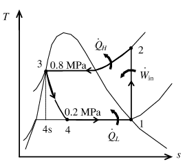
From Figure (2), write the specific enthalpy at state 3 is equal to state 4 due to throttling process.
Express the coefficient of performance.
Express the rate of heat supplied to the heated room.
Conclusion:
Refer Table A-12, “saturated refrigerant-134a-pressure table”, and write the properties corresponding to initial pressure of
Here, specific entropy at state 1 is
Refer Table A-13, “superheated refrigerant 134a”, and write the specific enthalpy at state 2 corresponding to pressure at state 2 of
Show the specific enthalpy at state 2 corresponding to specific entropy as in Table (2).
|
Specific entropy at state 2 |
Specific enthalpy at state 2 |
| 0.9185 | 267.34 |
| 0.9379 | |
| 0.9481 | 276.46 |
Use Excels and substitute the values from Table (2) in Equation (VI) to get,
Refer Table A-12, “saturated refrigerant-134a-pressure table”, and write the specific enthalpy at state 3 corresponding to pressure at state 3
Here, specific enthalpy at saturated liquid is
Since the specific enthalpy at state 3 is equal to state 4 due to throttling process.
Substitute
Substitute
Hence, the COP and the rate of heat supplied to the heated room is
Want to see more full solutions like this?
Chapter 11 Solutions
THERMODYNAMICS


- A commercial refrigerator with refrigerant-134a as the working fluid is used to keep the refrigerated space at 10°C by rejecting waste heat to cooling water that enters the condenser at 18°C at a rate of 0.25 kg/s and leaves at 26°C. The refrigerant enters the condenser at 1.2 MPa and 50°C and leaves at the same pressure subcooled by 5°C. If the compressor consumes 2.3 kW of power, determine the COP?arrow_forwardAn air conditioner using refrigerant-134a as the working fluid is used to keep the temperature of a room at 23°C by giving heat to the external environment at 37°C. The heat gain of the house from the walls and windows is 250 kJ/min; 900 W heat is emitted into the room from the computer, TV and lamps. The refrigerant enters the compressor with a flow rate of 100 L/min in the form of saturated vapor at 400 kPa pressure and leaves the compressor at 70°C at 1200 kPa pressure.a) Draw the cycle by showing the elements of the cycle.b) the actual COP value,c) The highest COP value,d) The smallest refrigerant can have for the same compressor inlet and outlet conditions.Calculate the volumetric flow.arrow_forwardConsider a refrigeration system using refrigerant-134a as the working fluid. If this refrigerator is to operate in an environment at 20°C, what is the minimum pressure to which the refrigerant should be compressed? Why?arrow_forward
- Refrigerant-134a at a rate of 0.08 kg/s enters the compressor of a refrigerator as superheated vapor at 0.18 MPa and 0 ℃ and leaves at 0.9 MPa and 80 ℃. The refrigerant is cooled in the condenser to 31.3 ℃ and 0.8 MPa and it is throttled to 0.18 MPa. Disregarding any heat transfer and pressure drops in the connecting lines between the components, Determine the coefficient of performance of the refrigerator.arrow_forwardA commercial refrigerator with refrigerant-134a as the working fluid is used to keep the refrigerated space at –35°C by rejecting waste heat to cooling water that enters the condenser at 18°C at a rate of 0.25 kg/s and leaves at 26°C. The refrigerant enters the condenser at 1.2 MPa and 50°C and leaves at the same pressure subcooled by 5°C. If the compressor consumes 3.3 kW of power, determine the mass flow rate of the refrigerant,arrow_forwardA commercial refrigerator with refrigerant-134a as the working fluid is used to keep the refrigerated space at –35°C by rejecting waste heat to cooling water that enters the condenser at 18°C at a rate of 0.25 kg/s and leaves at 26°C. The refrigerant enters the condenser at 1.2 MPa and 50°C and leaves at the same pressure subcooled by 5°C. If the compressor consumes 3.3 kW of power, determine the refrigeration load.arrow_forward
- Refrigerant R-134a enters the compressor of a refrigeration machine at 140 kPa pressure and -10°C temperature and exits at 1 MPa pressure. The volumetric flow of the refrigerant entering the compressor is 0.23 m3/minute. The refrigerant enters the throttling valve at 0.95 MPa pressure and 30°C, exiting the evaporator as saturated steam at -18°C. The adiabatic efficiency of the compressor is 78%. Show the cycle in the T-s diagram. a) Calculate the power required to start the compressor. b) Calculate the heat taken in a unit time from the cooled environment. COP=? c) Calculate between the evaporator and the compressor, how much the pressure of the refrigerant drops, and how much is the heat gain.arrow_forward2. A steam power plant operates on the Rankine cycle in which the steam enters the turbine at 16 MPa and 600°C and the condensate leaves the condenser at 10 kPa. If the isentropic efficiency of the turbine is 87 percent and the isentropic efficiency of the pump is 85 percent, determine (a) the thermal efficiency of the cycle and (b) the net power output of the plant for a mass flow rate of 15 kg/s.arrow_forwardR134a enters the condenser of a residential heat pump at 850 kPa and 70°C at a rate of 0.020 kg/s and leaves at 750 kPa and 2°C. The refrigerant enters the compressor at 180 kPa and 8.0°C. Determine (a) the isentropic efficiency of the compressor (in %), (b) the rate of heat supplied to the heated room (in kW) and (c) the COP of the heat pump. Disregard any heat loss in the expansion valve and compressor as well as the change in potential and kinetic energy of the refrigerant in any part of the cycle.arrow_forward
- Define the h-s diagram of the actual and isentropic processes of an adiabatic compressor.arrow_forwardDoes a Liquid-Dominant Geothermal Power Plant need both a condenser and a cooling tower? Or will either one do? And why.arrow_forwardDescribe the ideal process for an adiabatic nozzle, and define the isentropic efficiency for each device.arrow_forward
 Elements Of ElectromagneticsMechanical EngineeringISBN:9780190698614Author:Sadiku, Matthew N. O.Publisher:Oxford University Press
 Mechanics of Materials (10th Edition)Mechanical EngineeringISBN:9780134319650Author:Russell C. HibbelerPublisher:PEARSON
 Thermodynamics: An Engineering ApproachMechanical EngineeringISBN:9781259822674Author:Yunus A. Cengel Dr., Michael A. BolesPublisher:McGraw-Hill Education
 Control Systems EngineeringMechanical EngineeringISBN:9781118170519Author:Norman S. NisePublisher:WILEY
 Mechanics of Materials (MindTap Course List)Mechanical EngineeringISBN:9781337093347Author:Barry J. Goodno, James M. GerePublisher:Cengage Learning
 Engineering Mechanics: StaticsMechanical EngineeringISBN:9781118807330Author:James L. Meriam, L. G. Kraige, J. N. BoltonPublisher:WILEY