
Videos
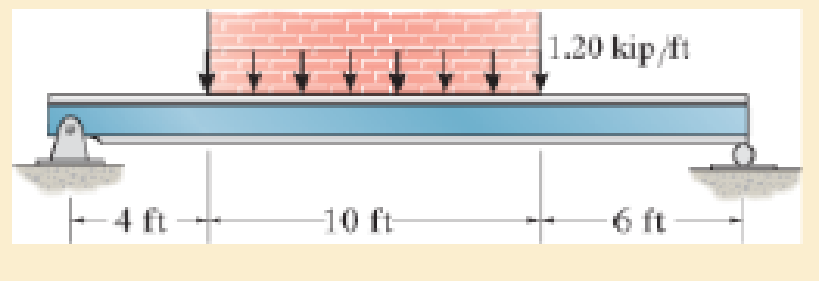
If the allowable bending stress is σallow = 22 ksi and the allowable shear stress is τallow =12 ksi, select the lightest wide-flange section with the shortest depth from Appendix B that will safely support the load. If there are several choices of equal weight, choose the one with the shortest height.

Learn your wayIncludes step-by-step video

Chapter 11 Solutions
Mechanics of Materials Plus Mastering Engineering with Pearson eText - Access Card Package (10th Edition)
Additional Engineering Textbook Solutions
Engineering Mechanics: Statics & Dynamics (14th Edition)
Engineering Mechanics: Statics
Automotive Technology: Principles, Diagnosis, and Service (5th Edition)
Engineering Mechanics: Dynamics (14th Edition)
Applied Fluid Mechanics (7th Edition)
Thinking Like an Engineer: An Active Learning Approach (3rd Edition)


- A11 Consider the cutaway diagram provided above. Using this, identify and describe a structural component or sub-structure that carries bending. You should sketch and describe an idealisation of the structural component suitable for analysing the bending response, and describe how the structural component may fail under bending.arrow_forwardIf the allowable normal stress is 120MPa and the allowable shear stress is 60MPa, what is the resultant force at the support A?arrow_forwardAt a given 7 locations/sections (0,1,2,3,4,5,6) on a beam of uniform I-section, the beam is subjected to a shear force of 100 kN. Plot a curve to show the variation of shear stress across the section and hence determine the ratio of the maximum shear stress to the mean shear stress given as;arrow_forward
- Determine the maximum bending stress in the brass. Determine the maximum bending stress in the steel. Determine the stress in the brass at the seam where the brass and steel are bonded together. Determine the stress in the steel at the seam where the brass and steel are bonded together.arrow_forwardConsidering only pure bending, determine the minimum section modulus for the component and loads shown. Assume ?? of 36,000 psi and a factor of safety of 1.67. (Hint: the part does not have to exceed the allowable stress) Do not forget to draw and calculate the diagram of shear force and bending moment The distances in the beam are in feet. The value of the load P1 and P4 is 2 kips. The value of the loads P2 and P3 is 6 kipsarrow_forwardIf a loaded beam is cut at a certain point and the left section is considered, the internal forces that will be exposed are? A downward internal shear and a counterclockwise internal moment An upward internal shear and a counterclockwise internal moment An upward internal shear and a clockwise internal moment A downward internal shear and a clockwise internal momentarrow_forward
- Define the shear and bending-moment diagrams.arrow_forwardThe channel section shown below is simply supported over a span of 5 m and carries a uniformly distributed load of 15 kN/m run over its whole length. Find shearing-stress distribution diagram at the point of maximum shearing force and mark important values. Determine the ratio of the maximum shearing stress to the average shearing stress.arrow_forwardRailroad ties must be designed to resist large shear loads. If the tie shown in Fig. E1 below is subjected to the 30 kip rail loadings and the gravel bed exerts a distributed reaction as shown, determine: The maximum shear force in the tie. The maximum shear stress in the tie. The maximum positive and negative bending moments in the tie. The maximum tensile and compressive bending stresses in the tie.arrow_forward
- find the average shear stress on the section of the inclined member if we were to cut it horizontally.arrow_forwardThese garden shears were manufactured using an inferior material. Using a loading of 50 lb applied normal to the blades, and appropriate dimensions for the shears, determine the absolute maximum bending stress in the material and show why the failure occurred at the critical location on the handle.arrow_forwardThe maximum torsional shear stress of a shaft with diameter D can be found at what distance from the center of the shaft?arrow_forward
 Elements Of ElectromagneticsMechanical EngineeringISBN:9780190698614Author:Sadiku, Matthew N. O.Publisher:Oxford University Press
 Mechanics of Materials (10th Edition)Mechanical EngineeringISBN:9780134319650Author:Russell C. HibbelerPublisher:PEARSON
 Thermodynamics: An Engineering ApproachMechanical EngineeringISBN:9781259822674Author:Yunus A. Cengel Dr., Michael A. BolesPublisher:McGraw-Hill Education
 Control Systems EngineeringMechanical EngineeringISBN:9781118170519Author:Norman S. NisePublisher:WILEY
 Mechanics of Materials (MindTap Course List)Mechanical EngineeringISBN:9781337093347Author:Barry J. Goodno, James M. GerePublisher:Cengage Learning
 Engineering Mechanics: StaticsMechanical EngineeringISBN:9781118807330Author:James L. Meriam, L. G. Kraige, J. N. BoltonPublisher:WILEY