Concept explainers
Videos
The assembly ABC is made of a steel for which E = 200 GPa and σY = 320 MPa. Knowing that a strain energy of 5 J must be acquired by the assembly as the axial load P is applied, determine the factor of safety with respect to permanent deformation when (a) x = 300 mm, (b) x = 600 mm.
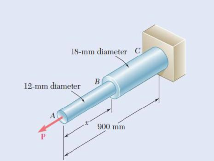
Fig. P11.15
(a)
Find the factor of safety with respect to permanent deformation when
Answer to Problem 15P
The factor of safety with respect to permanent deformation is
Explanation of Solution
Given information:
The diameter of the steel rod AB is
The diameter of the steel rod BC is
The length of the rod AB is
The length of the rod BC is
The modulus of elasticity of the steel is
The yield strength of steel is
The strain energy acquired by the assembly is
Calculation:
Calculate the area of the rod (A) as shown below.
For the steel rod AB.
Substitute
For the steel rod BC.
Substitute
Hence, the minimum area of the rod
Calculate the load
Substitute
Calculate the strain energy
Calculate the strain energy for rod ABC as shown below.
Substitute
Calculate the factor of safety
Substitute
Therefore, the factor of safety with respect to permanent deformation is
(b)
Find the factor of safety with respect to permanent deformation when
Answer to Problem 15P
The factor of safety with respect to permanent deformation is
Explanation of Solution
Given information:
The diameter of the steel rod AB is
The diameter of the steel rod BC is
The length of the rod AB is
The length of the rod BC is
The modulus of elasticity of the steel is
The yield strength of steel is
The strain energy acquired by the assembly is
Calculation:
Refer to part (a).
The area of the steel rod AB is
The area of the steel rod BC is
The load acting on the assembly is
Calculate the strain energy
Substitute
Calculate the factor of safety
Substitute
Therefore, the factor of safety with respect to permanent deformation is
Want to see more full solutions like this?
Chapter 11 Solutions
Loose Leaf For Mechanics Of Materials Format: Looseleaf


- Two links BF are made of steel with a 450-MPa ultimate normal stress and has a 6x12–mm uniform rectangular cross section. Links BF are connected to members ABD and CDEF by 8-mm diameter pins; ABD and CDEF are connected together by a 10-mm diameter pin; CDEF is connected to the support by a 10-mm diameter pin; all of the pins are made of steel with a 170 MPa ultimate shearing stress. Knowing that a factor of safety of 3 is desired, determine the largest load P that may be appliedarrow_forwardA force P and a force Q, applied via a nut, are acting on the arm attached to the end of a shaft made of steel. The strain gauge readings on point A of the shaft show the following deformation values: ε1 = 630x10-6, ε2 = 600x10-6, and ε3 = - 189x10-6. Determine the magnitudes of the applied forces P and Q (E = 200 GPa, υ = 0.3).arrow_forwardDetermine the width and thickness of the leaves (in mm) of a leaf spring using the following specifications: Total load = 140 kN; Number of springs supporting the load = 4; Maximum number of leaves = 10; Span of the spring = 1000 mm; Permissible deflection = 80 mm; Modulus of elasticity, E = 200 kN/mm2; and allowable stress in spring material is 600 MPa.arrow_forward
- Knowing that a 0.02-in. gap exists when the temperature is 75°F, determine (a) the temperature at which the normal stress in the alumi-num bar will be equal to –11 ksi, (b) the corresponding exact length of the aluminum bar.arrow_forwardEach of the four vertical Ilinks has an 8 x 36-mm uniform rectangular cross section and each of the four pins has a 16-mm diameter. Take P= 19 kN. 0.4 m C 0.25 m 0.2 m B. P Determine the average bearing stress at Bin member ABC, knowing that this member has a 10 x 50-mm uniform rectangular cross section. MPa. The average bearing stress at Bin member ABC is.arrow_forwardThe pipe assembly shown is subjected to a force F = 7 kN and P = 14 kN. It is made of steel with Sy = 250 MPa. Determine the safety factor at point H using the maximum shear stress theory. Select one: a. NH = 6.427 b. NH = 3.570 c. NH = 5.355 d. NH = 4.590arrow_forward
- A large water tank that has a capacity to carry 20,000 liters is to be supported by four cylindrical posts. These four support posts are made of plain carbon (1045) steels with the yield and tensile strengths of 310 MPa and 565 MPa, respectively. Determine the minimum required diameter of the post assuming a factor of safety of 5.arrow_forwardThe normal strain in a suspended bar of material of varying cross section due to its own weight is given by the expression γy/3E where γ = 2.9 lb/in.3 is the specific weight of the material, y = 3.4 in. is the distance from the free (i.e., bottom) end of the bar, L = 17 in. is the length of the bar, and E = 24000 ksi is a material constant. Determine, (a) the change in length of the bar due to its own weight. (b) the average normal strain over the length L of the bar. (c) the maximum normal strain in the bar.arrow_forwardThe pipe assembly shown is subjected to a force F = 400 N. The pipe has an inner diameter of 20 mm and an outer diameter of 30 mm. It is made of steel with Sy = 250 MPa. Determine the safety factor at point A using the maximum shear stress theory. Select one: a. NA = 1.843 b. NA = 3.224 c. NA = 2.580 d. NA = 4.299arrow_forward
- Determine the elongation of an aluminium hollow cylinder of an inner diameter of 1.1 cm & the external diameter of 22.7 mm is subjected to an elastic tensile load of 271 kN. Take the elastic modulus of the aluminum specimen as 73 GPa and the initial length of the hollow cylinder as 186 mm. Solution: i) Cross-sectional Area (in mm2) = ii) Stress-induced (in N/mm2) = iii) Strain-induced (at least 3 decimal places accuracy)= iv) Elongation (in mm) =arrow_forwardIn many situations physical constraints prevent strain from occurring in a given direction. For example, εz= 0 in the case shown, where longitudinal movement of the long prism is prevented at every point. Plane sections perpendicular to the longitudinal axis remain plane and the same distance apart. Show that for this situation, which is known as plane strain, we can express σz, εx, and εy as followsarrow_forwardDetermine the thickness of a 130 mm wide uniform plate for safe continuous operation if the plate is to be subjected to a tensile load that has a maximum value of 260 kN and a minimum value of 110 kN. The properties of the plate material are as follows: Endurance limit stress = 235 MPa, and Yield point stress = 310 MPa. The factor of safety based on yield point may be taken as 1.4.arrow_forward
 Elements Of ElectromagneticsMechanical EngineeringISBN:9780190698614Author:Sadiku, Matthew N. O.Publisher:Oxford University Press
 Mechanics of Materials (10th Edition)Mechanical EngineeringISBN:9780134319650Author:Russell C. HibbelerPublisher:PEARSON
 Thermodynamics: An Engineering ApproachMechanical EngineeringISBN:9781259822674Author:Yunus A. Cengel Dr., Michael A. BolesPublisher:McGraw-Hill Education
 Control Systems EngineeringMechanical EngineeringISBN:9781118170519Author:Norman S. NisePublisher:WILEY
 Mechanics of Materials (MindTap Course List)Mechanical EngineeringISBN:9781337093347Author:Barry J. Goodno, James M. GerePublisher:Cengage Learning
 Engineering Mechanics: StaticsMechanical EngineeringISBN:9781118807330Author:James L. Meriam, L. G. Kraige, J. N. BoltonPublisher:WILEY