Videos
Find the strain energy of the prismatic beam AB.
Answer to Problem 40P
The strain energy of the prismatic beam AB is
Explanation of Solution
Given information:
Taking into account the effect of both normal and shearing stresses.
Calculation:
Calculate the moment of inertia (I) for the rectangular cross section as shown below.
Here, b is the width of the cross section and d is the depth of the cross section.
Calculate the area of the cross section (A) as shown below.
Calculate the centroid (c) as shown below.
Calculate the reactions as shown below.
Take moment about B is Equal to zero.
Summation of forces along vertical direction is Equal to zero.
Calculate the shear force as shown below.
Shear force at A is
Shear force at B is
Calculate the bending moment as shown below.
Bending moment at A is
Bending moment at B is
Sketch the shear force and bending moment diagram as shown in Figure 1.
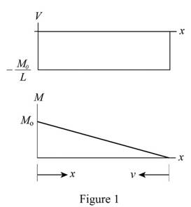
Refer to Figure 1.
Maximum shear force
Maximum bending moment
Bending moment at a distance
Calculate the strain energy due to bending
Substitute
Substitute
Calculate the shear stress
Calculate the strain energy density
Here, G is the modulus of rigidity.
Substitute
Substitute
The value of
Differentiate both sides of the Equation as shown below.
Calculate the strain energy due to shear as shown below.
Substitute
Substitute
Calculate the total strain energy as shown below.
Substitute
Hence, the strain energy of the prismatic beam AB is
Want to see more full solutions like this?
Chapter 11 Solutions
Loose Leaf For Mechanics Of Materials Format: Looseleaf


- 7) The strain of a component, which has a tensile modulus of 4 X 10⁵ MPa, and subjected to a stress of 6000KPa, is a. 0.000015 b. 0.00015 c. 0.00003 d. 0.003arrow_forwardStiffness is the property that enables material to withstand high stress without great strain. it is a resistance to any sort of deformation and is a function of the modulus of elasticity, E of the material True or falsearrow_forwardIn many situations physical constraints prevent strain from occurring in a given direction. For example, εz= 0 in the case shown, where longitudinal movement of the long prism is prevented at every point. Plane sections perpendicular to the longitudinal axis remain plane and the same distance apart. Show that for this situation, which is known as plane strain, we can express σz, εx, and εy as followsarrow_forward
- In the graft, the 6-meter-high arm is manufactured using the l profile given below. It is fixed to both ends of the arm with a built-in support. If the yield strength of the material is σy=400 MPa Elasticity modulus E=2*105 MPa If the safety factor used in the design is 2.5, the arm in question is What is the highest axial load it can safely carry?arrow_forwardmaterials mechanics A bar of circular cross section is made of an isotropic, linearly elastic material. The material has an elastic limit of 360 MPa. The bar is subjected to two equal and opposite bending moments M2=12 kNm and two equal and opposite torsional moments M1=16 kNm. Determine the minimum diameter of the bar for a safe design using the following factor of safety: F.S=3.arrow_forwardThe error in a measurement due to strain when using a tape measure depends on the material that it is made of. For a tape with a cross section of 10 mm by 0.7 mm, calculate how much error is introduced in inches into the measurement at a 300 ft length if the tape is pulled with 80 N and if the tape is made of: a) mild steel (E = 30 x 10^6 psi), b) polycrystalline aluminum (E = 10 x 10^6 psi) c) fiberglass composite (E = 3.5 x 10^6 psi in the long direction)arrow_forward
- The Poisson’s ratio, μ of common engineering materials lies in the range: 0 1.2 0 0.5 -1 1 - 0.5 0.5arrow_forwardA steel rod is subjected to a gradually applied load (F) which gave a rise to a maximum stress of 200 MPa. The rod is 250 mm long and one part of its length is square and the remainder is circular with a diameter of 25 mm. If the total strain energy in the rod and modulus elasticity of the material is 1.3 J and 200 GPa, determine the following:1.The applied load F2.The total extension of the bar3.The length of the square portion of the bar4.The suddenly applied load that will induce the same amount of energy 5.The load that falls from a height of 8 mm induces 1,3 J in the bar.arrow_forwardUse the principle of Strain energy due to direct stresses Chapter 8 strain energy due to direct stresses Strength of materials 2 And clarify the part the part of the maximum amount of energyarrow_forward
- The general equation that describes the relationship between the stress and the strain for ductile materials is known as: Young’s modulus Bayes’ theorem Hooke’s lawarrow_forwardSintered silicon nitride parts are expected to experience tensile stresses 50% of the ultimate tensile strength of the material. What will be the maximum allowable size of internal flaws for these parts not to fail in service? Given the following properties of the material: Specific surface energy: 0.3 J/m2 its Youngs Modulus: 304 GPa Ultimate tensile Strength: 570 MPa Select one: a. 1.43 µm b. 0.71 µm c. 15 µm d. 85 µm e. 9.5 µmarrow_forwardPART 1 answer Ay=45kN Dy=140kn PART 2 Determine the shear force acting at each of the following locations: (a) x = 2m (b) x = 6m (c) x = 9m (d) x = 12m My Answer: (a) V= 45kN (b) V= -20kN (c) V= -110kN (d) V= 30kN PART 3 Determine the bending moment acting at each of the following locations: (a) x=4m (b) x = 8 m (c) x = 10 m When entering your answers, use the bending moment sign convention. Need Answers: (a) M= ________________kN-m (b) M= ________________kN-m (c) M= ________________kN-marrow_forward
 Elements Of ElectromagneticsMechanical EngineeringISBN:9780190698614Author:Sadiku, Matthew N. O.Publisher:Oxford University Press
 Mechanics of Materials (10th Edition)Mechanical EngineeringISBN:9780134319650Author:Russell C. HibbelerPublisher:PEARSON
 Thermodynamics: An Engineering ApproachMechanical EngineeringISBN:9781259822674Author:Yunus A. Cengel Dr., Michael A. BolesPublisher:McGraw-Hill Education
 Control Systems EngineeringMechanical EngineeringISBN:9781118170519Author:Norman S. NisePublisher:WILEY
 Mechanics of Materials (MindTap Course List)Mechanical EngineeringISBN:9781337093347Author:Barry J. Goodno, James M. GerePublisher:Cengage Learning
 Engineering Mechanics: StaticsMechanical EngineeringISBN:9781118807330Author:James L. Meriam, L. G. Kraige, J. N. BoltonPublisher:WILEY