
Connect 1-semester Access Card For Mechanics Of Materials - 2016 Update
7th Edition
ISBN: 9781259968006
Author: Ferdinand P. Beer, E. Russell Johnston Jr., John T. DeWolf, David Mazurek
Publisher: McGraw-Hill Education
expand_more
expand_more
format_list_bulleted
Concept explainers
Videos
Textbook Question
Chapter 11.9, Problem 95P
For the beam and loading shown, determine the slope at end A. Use E = 200 GPa.
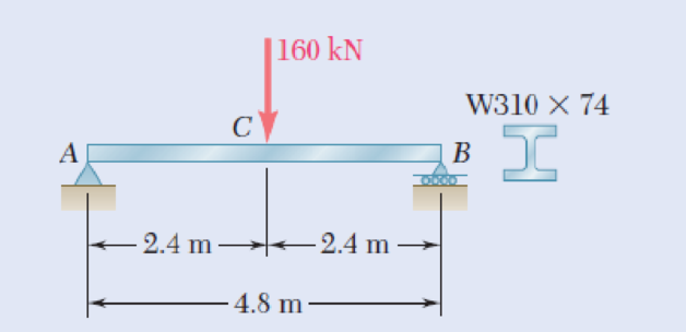
Fig. P11.95
Expert Solution & Answer
Want to see the full answer?
Check out a sample textbook solution
Students have asked these similar questions
The center span of the Verrazano-Narrows Bridge consists of two uniform roadways suspended from four cables. The design of the bridge allows for the effect of extreme temperature changes that cause the sag of the center span to vary from hw= 386 ft in winter to hs= 394 ft in summer. Knowing that the span is L = 4260 ft, determine the change in length of the cables due to extreme temperature changes.
13.62
A bumper made of a hard spring is to stop a 30ton gondala car which is traveling at 4ft/s as shown. Such a spring developes a restoring force F=100x+12x^3 kips when it si compressed by an amount of x ft. Determine the maximum deflection of the bumper.
A 40-lb weight is dropped from a height of h = 2 ft. A 40-lb weight is dropped from a height of h = 2 ft onto the center of the cantilevered A992 steel beam. If the beam is a W10 * 15, determine the maximum bending stress in the beam. onto the center of the cantilevered A992 steel beam. If the beam is a W10 * 15, determine the maximum bending stress in the beam.
Chapter 11 Solutions
Connect 1-semester Access Card For Mechanics Of Materials - 2016 Update
Ch. 11.3 - Determine the modulus of resilience for each of...Ch. 11.3 - Determine the modulus of resilience for each of...Ch. 11.3 - Determine the modulus of resilience for each of...Ch. 11.3 - Determine the modulus of resilience for each of...Ch. 11.3 - The stress-strain diagram shown has been drawn...Ch. 11.3 - The stress-strain diagram shown has been drawn...Ch. 11.3 - Prob. 7PCh. 11.3 - Prob. 8PCh. 11.3 - Using E = 29 106 psi, determine (a) the strain...Ch. 11.3 - Using E = 200 GPa, determine (a) the strain energy...
Ch. 11.3 - A 30-in. length of aluminum pipe of...Ch. 11.3 - A single 6-mm-diameter steel pin B is used to...Ch. 11.3 - Prob. 13PCh. 11.3 - Prob. 14PCh. 11.3 - The assembly ABC is made of a steel for which E =...Ch. 11.3 - Show by integration that the strain energy of the...Ch. 11.3 - Prob. 17PCh. 11.3 - Prob. 18PCh. 11.3 - Prob. 19PCh. 11.3 - 11.18 through 11.21 In the truss shown, all...Ch. 11.3 - Prob. 21PCh. 11.3 - Each member of the truss shown is made of aluminum...Ch. 11.3 - Each member of the truss shown is made of aluminum...Ch. 11.3 - 11.24 through 11.27 Taking into account only the...Ch. 11.3 - Prob. 25PCh. 11.3 - 11.24 through 11.27 Taking into account only the...Ch. 11.3 - 11.24 through 11.27 Taking into account only the...Ch. 11.3 - Prob. 28PCh. 11.3 - Prob. 29PCh. 11.3 - Prob. 30PCh. 11.3 - 11.30 and 11.31 Using E = 200 GPa, determine the...Ch. 11.3 - Assuming that the prismatic beam AB has a...Ch. 11.3 - Prob. 33PCh. 11.3 - The design specifications for the steel shaft AB...Ch. 11.3 - Show by integration that the strain energy in the...Ch. 11.3 - The state of stress shown occurs in a machine...Ch. 11.3 - Prob. 37PCh. 11.3 - The state of stress shown occurs in a machine...Ch. 11.3 - Prob. 39PCh. 11.3 - Prob. 40PCh. 11.3 - Prob. 41PCh. 11.5 - A 5-kg collar D moves along the uniform rod AB and...Ch. 11.5 - The 18-lb cylindrical block E has a horizontal...Ch. 11.5 - The cylindrical block E has a speed v0 =16 ft/s...Ch. 11.5 - Prob. 45PCh. 11.5 - Prob. 46PCh. 11.5 - The 48-kg collar G is released from rest in the...Ch. 11.5 - Prob. 48PCh. 11.5 - Prob. 49PCh. 11.5 - Prob. 50PCh. 11.5 - Prob. 51PCh. 11.5 - The 2-kg block D is dropped from the position...Ch. 11.5 - The 10-kg block D is dropped from a height h = 450...Ch. 11.5 - Prob. 54PCh. 11.5 - A 160-lb diver jumps from a height of 20 in. onto...Ch. 11.5 - Prob. 56PCh. 11.5 - A block of weight W is dropped from a height h...Ch. 11.5 - 11.58 and 11.59 Using the method of work and...Ch. 11.5 - 11.58 and 11.59 Using the method of work and...Ch. 11.5 - 11.60 and 11.61 Using the method of work and...Ch. 11.5 - 11.60 and 11.61 Using the method of work and...Ch. 11.5 - 11.62 and 11.63 Using the method of work and...Ch. 11.5 - 11.62 and 11.63 Using the method of work and...Ch. 11.5 - Using the method of work and energy, determine the...Ch. 11.5 - Using the method of work and energy, determine the...Ch. 11.5 - The 20-mm diameter steel rod BC is attached to the...Ch. 11.5 - Torques of the same magnitude T are applied to the...Ch. 11.5 - Prob. 68PCh. 11.5 - The 20-mm-diameter steel rod CD is welded to the...Ch. 11.5 - The thin-walled hollow cylindrical member AB has a...Ch. 11.5 - 11.71 and 11.72 Each member of the truss shown has...Ch. 11.5 - 11.71 and 11.72 Each member of the truss shown has...Ch. 11.5 - Each member of the truss shown is made of steel...Ch. 11.5 - Each member of the truss shown is made of steel....Ch. 11.5 - Each member of the truss shown is made of steel...Ch. 11.5 - The steel rod BC has a 24-mm diameter and the...Ch. 11.9 - 11.77 and 11.78 Using the information in Appendix...Ch. 11.9 - 11.77 and 11.78 Using the information in Appendix...Ch. 11.9 - 11.79 through 11.82 For the beam and loading...Ch. 11.9 - 11.79 through 11.82 For the beam and loading...Ch. 11.9 - 11.79 through 11.82 For the beam and loading...Ch. 11.9 - 11.79 through 11.82 For the beam and loading...Ch. 11.9 - 11.83 through 11.85 For the prismatic beam shown,...Ch. 11.9 - 11.83 through 11.85 For the prismatic beam shown,...Ch. 11.9 - 11.83 through 11.85 For the prismatic beam shown,...Ch. 11.9 - 11.86 through 11.88 For the prismatic beam shown,...Ch. 11.9 - 11.86 through 11.88 For the prismatic beam shown,...Ch. 11.9 - 11.86 through 11.88 For the prismatic beam shown,...Ch. 11.9 - For the prismatic beam shown, determine the slope...Ch. 11.9 - For the prismatic beam shown, determine the slope...Ch. 11.9 - For the beam and loading shown, determine the...Ch. 11.9 - For the beam and loading shown, determine the...Ch. 11.9 - 11.93 and 11.94 For the beam and loading shown,...Ch. 11.9 - 11.93 and 11.94 For the beam and loading shown,...Ch. 11.9 - For the beam and loading shown, determine the...Ch. 11.9 - For the beam and loading shown, determine the...Ch. 11.9 - Prob. 97PCh. 11.9 - For the beam and loading shown, determine the...Ch. 11.9 - 11.99 and 11.100 For the truss and loading shown,...Ch. 11.9 - 11.99 and 11.100 For the truss and loading shown,...Ch. 11.9 - 11.101 and 11.102 Each member of the truss shown...Ch. 11.9 - 11.101 and 11.102 Each member of the truss shown...Ch. 11.9 - 11.103 and 11.104 Each member of the truss shown...Ch. 11.9 - 11.103 and 11 104 Each member of the truss shown...Ch. 11.9 - A uniform rod of flexural rigidity EI is bent and...Ch. 11.9 - For the uniform rod and loading shown and using...Ch. 11.9 - For the beam and loading shown and using...Ch. 11.9 - Two rods AB and BC of the same flexural rigidity...Ch. 11.9 - Three rods, each of the same flexural rigidity EI,...Ch. 11.9 - Three rods, each of the same flexural rigidity EI,...Ch. 11.9 - 11.111 through 11.115 Determine the reaction at...Ch. 11.9 - 11.111 through 11.115 Determine the reaction at...Ch. 11.9 - 11.111 through 11.115 Determine the reaction at...Ch. 11.9 - 11.111 through 11.115 Determine the reaction at...Ch. 11.9 - 11.111 through 11.115 Determine the reaction at...Ch. 11.9 - For the uniform beam and loading shown, determine...Ch. 11.9 - 11.117 through 11.120 Three members of the same...Ch. 11.9 - 11.117 through 11.120 Three members of the same...Ch. 11.9 - 11.117 through 11.120 Three members of the same...Ch. 11.9 - 11.117 through 11.120 Three members of the same...Ch. 11.9 - 11.121 and 11.122 Knowing that the eight members...Ch. 11.9 - 11.121 and 11.122 Knowing that the eight members...Ch. 11 - Rod AB is made of a steel for which the yield...Ch. 11 - Each member of the truss shown is made of steel...Ch. 11 - The ship at A has just started to drill for oil on...Ch. 11 - Collar D is released from rest in the position...Ch. 11 - Each member of the truss shown is made of steel...Ch. 11 - A block of weight W is placed in contact with a...Ch. 11 - Two solid steel shafts are connected by the gears...Ch. 11 - A 160-lb diver jumps from a height of 20 in. onto...Ch. 11 - For the prismatic beam shown, determine the slope...Ch. 11 - A disk of radius a has been welded to end B of the...Ch. 11 - A uniform rod of flexural rigidity EI is bent and...Ch. 11 - The steel bar ABC has a square cross section of...
Knowledge Booster


Learn more about
Need a deep-dive on the concept behind this application? Look no further. Learn more about this topic, mechanical-engineering and related others by exploring similar questions and additional content below.Similar questions
- Determine the absolute maximum bending moment in a 60 ft long simply supported beam due to the series of four moving concentrated loads shown in Fig. P9.14.arrow_forwardDetermine the maximum deflection of a simply supported beam, 6 m long and carrying a uniformly distributed load of 200 N/m applied over its entire length.arrow_forward*P=51*Plot the shear and moment diagram of each memberarrow_forward
- 1. A sling shot was released in a vertical direction using a rubber band having an equivalent spring constant of 2N/mm. If the deflection of the rubber band amounts to 10cm and the mass of the stone is 21g, determine the maximum height (above the undeflected position of the sling) the shot can reach. Derive with the formula below, show the cancellation, explain the step by step and DRAW a free body diagram/figure. Refer with this: PE1 + KE1 + U1 + WF1 + Q1 + W1 = PE2 + KE2 + U2 + WF2 + Q2 + W2 + E losses.arrow_forwardThe beam shown has the following data:w1 = 10.0 kN/mw2 = 30.4 kN/mx = 14.8 my = 4.8 mDetermine the magnitude of the reaction force at C in kNarrow_forwardThe rod ABC is made of an aluminum for which E = 71.4 GPa. Knowing that P = 7.94 kNand Q = 49.88 kN,determine the deflection (in μm) of point B if y = 0.47 and z = 0.54. Round off the final answer in four decimal places.arrow_forward
- Develop an expression for the shear force V(x) as a function of position (x) along the beam.arrow_forwardA cantilever beam, 6m long, fixed at point A and free at point B, is subjected to a downward uniform load 50 kN/m throughout the beam. Determine the tangential deviation of A wrt B. Answer: _____/EIarrow_forwardA semicircular rod of weight W and uniform cross section is supported as shown. Determine the bending moment at point J w hen 0=60°.Fig. P7.23arrow_forward
arrow_back_ios
SEE MORE QUESTIONS
arrow_forward_ios
Recommended textbooks for you
 Elements Of ElectromagneticsMechanical EngineeringISBN:9780190698614Author:Sadiku, Matthew N. O.Publisher:Oxford University Press
 Mechanics of Materials (10th Edition)Mechanical EngineeringISBN:9780134319650Author:Russell C. HibbelerPublisher:PEARSON
 Thermodynamics: An Engineering ApproachMechanical EngineeringISBN:9781259822674Author:Yunus A. Cengel Dr., Michael A. BolesPublisher:McGraw-Hill Education
 Control Systems EngineeringMechanical EngineeringISBN:9781118170519Author:Norman S. NisePublisher:WILEY
 Mechanics of Materials (MindTap Course List)Mechanical EngineeringISBN:9781337093347Author:Barry J. Goodno, James M. GerePublisher:Cengage Learning
 Engineering Mechanics: StaticsMechanical EngineeringISBN:9781118807330Author:James L. Meriam, L. G. Kraige, J. N. BoltonPublisher:WILEY
Elements Of Electromagnetics
Mechanical Engineering
ISBN:9780190698614
Author:Sadiku, Matthew N. O.
Publisher:Oxford University Press
Mechanics of Materials (10th Edition)
Mechanical Engineering
ISBN:9780134319650
Author:Russell C. Hibbeler
Publisher:PEARSON
Thermodynamics: An Engineering Approach
Mechanical Engineering
ISBN:9781259822674
Author:Yunus A. Cengel Dr., Michael A. Boles
Publisher:McGraw-Hill Education
Control Systems Engineering
Mechanical Engineering
ISBN:9781118170519
Author:Norman S. Nise
Publisher:WILEY
Mechanics of Materials (MindTap Course List)
Mechanical Engineering
ISBN:9781337093347
Author:Barry J. Goodno, James M. Gere
Publisher:Cengage Learning
Engineering Mechanics: Statics
Mechanical Engineering
ISBN:9781118807330
Author:James L. Meriam, L. G. Kraige, J. N. Bolton
Publisher:WILEY
Solids: Lesson 53 - Slope and Deflection of Beams Intro; Author: Jeff Hanson;https://www.youtube.com/watch?v=I7lTq68JRmY;License: Standard YouTube License, CC-BY