
Concept explainers
Videos
Mechanical/Aerospace Engineering
Consider the three mass-four spring system in Fig. P12.37. Determining the equations of motion from
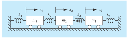
FIGURE P12.37
Where
At a specific time when x 1 5 0.05 m, x 2 5 0.04 m, and x 3 5 0.03 m, this forms a tridiagonal matrix. Solve for the acceleration of each mass.
Want to see the full answer?
Check out a sample textbook solution
Chapter 12 Solutions
EBK NUMERICAL METHODS FOR ENGINEERS


- QUESTION 18 The flywheel in Figure Q18 consists of two plates of mass m = 64 kg and thickness w = 0.050 m which are connected by arms of length 1 = 0.48 m into a rotating axis. An increasing moment M (N-m) is applied about the axis according to the expression M = 5t where t (s) is the time. Determine the time duration needed to accelerate the flywheel such that the plates reach a tangential velocity 20.0 m-s-1, if their initial velocity at time zero is 10 m-s-1. Provide only the numerical value (in seconds) to two decimal places (e.g. 10.25) and do not include the units in the answer box. m 1 M Figure Q18: Accelerating flywheel 1 marrow_forward22. Two springs with different spring constants are connected in three ways, as shown. KA kB kc eeeeeeeeee www. mom www. In the second case, the springs are connected to opposite ends of a string, which runs under a massless frictionless pulley. In each case, the two springs act like a single spring with an effective spring constant KA, KB, or kc. Which of the following is correct? (A) KA > kB > kc (B) kA>kc> kB (C) kc > kB> kA (D) kc > kA> kB (E) kB > KA >KCarrow_forward950g static mass Static Force Exerted by the Spring Time to Complete 60 Revolutions 39 sec Angular Velocity of the Rotating Mass Radius of Rotation for the Rotating Mass .179 m Mass of the Rotating Mass . 449 kg Centripetal Force Exerted on the Rotating Mass % Difference Between the Static and Centripetal Forcesarrow_forward
- 1. Assuming the velocity of B=0.7 m/s after dropping 480 mm. Complete the following: a. Determine the spring constant such that all conditions mentioned above are met b. Using you value from part a, determine distacne B will drop if lowered slowly Notes: System is initially at rest Spring free length Cylinder mass - 25 kg Cylinder radius = 400 mm Ic cylinder 1.2 kg.m² 2 300 mm A Radius of pulley = 100 mm Ic value for pulley 0.5 kg.m² B10 kg Bearrow_forward1. The displacement formulation for a plane truss is similar to that of a mass-spring system. The differences are: (1) the stiffnesses of the members are k;= (E A/L);, where E is the modulus of elasticity, A represents the cross-sectional area and L is the length of the member; (2) there are two components of displacement at each joint. For the statically indeterminate truss shown the displacement formulation yields the symmetric equations Ku = p. where k;= (E A/L), where E is the modulus of elasticity, A represents the cross-sectional area and L is the length of the member; (2) there are two components of displacement at each joint. For the statically indeterminate truss shown the displacement formulation yields the symmetric equations Ku=p. where: 27.58 7.004 -7.004 0.0000 0.00007 7.004 29.57 -5.253 0.0000 -24.32 K= -7.004 -5.253 29.57 0.0000 0.0000 MN/m 0.0000 0.0000 0.0000 27.58 -7.004 0.0000 -24.32 0.0000 -7.004 29.57 Determine the displacements u; of the joints. P= 000-45] KN…arrow_forwardConsider a mass-spring system shown below. X1 m k₁ ooooo The system model is given by d²x m m₁ 1 d1² dx, 2 di² 1 · + (k₁₂ + k₂) x ₂ −k ₂x₂=F₁ (1) 1 k₂ ooooo F₁ k₂x₂ + (k₂ + k ₂) x₂ = F₂(t) k₂ +k z 2 m_s (m_s²³ + k₁+k₂ ²+k₁ + k ₂ ) ( m ₂s ² + k₂ + k ₂) -k 2 where F₁(t) and F₂(t) are the inputs to the system. Find the transfer function X₁(s)/F₁(s). k ₂ (m₁s²+k₁+k₂) (m₂s² + k ₂2 +k₂ ) − k²/ 2 ₁s² + k ₁+k₂) 1 (m₂x²+₁+k₂) (m₂x²+k₂+^₂)=R} 2 ) ( m²₂ s² + k₂ + k ₂ 1 2 m₂ k ₁+k₂ 1 (m₁s²+k₁ + k₂) (m₂s² + k₂ + k 3) − k ²/ k 3 (m₂x²+k₂+k₂) (m₂x²+k₂+k₂) −R} k ² (m₂s² + k ₂+k₂) (m₂x²+k₂ +k₂) (m₂x²+k₂+A₂)-R² 3) k3 ooooo F₂arrow_forward
- A block of mass m = 1.2Kg is on a plane %3D inclined at 30 degrees for which uc = 0.11. The block is connected to a spring of constant K = 3.2 N / m, by a rope passing, without slipping, by a pulley. The pulley is a disc of 0.8Kg and 0.14m radius. If the system is initially at rest and the spring has zero elongation, what is the block velocity modulus when the block has slid 0.25m down the inclined plane? k=3,2 N/m 130° A Figure 11.75arrow_forwardNo. 15 From the table below, what is the initial tension required for the spring in letter (D)? Hooke's Law Force Constant (N/m) Hanging Hanger (g) | Mass (g) Mass Elongation (cm) Initial Force (N) Standard Experimental Tension (N) 10.0 (A) 0.52 5.00 10.0 (C) (D) 20.0 (B) 1.52 Percent Error (%) (E)arrow_forwardF y A → X CC BY UBC Engineering Your team is prototyping a simple braking system for your model car. The 2.2 kg wheel with a radius of rad r = 0.25 m is rotating at w = 5 A servo motor can apply a variable force F, which in its first two seconds of operation is equal to F N. If the coefficient of kinetic friction between the braking arm and the wheel is uk 10t N and afterwards is equivalent to a constant force of F = 20 0.25, determine the time needed for the wheel to come to a full stop. The point of contact P between the wheel and the - 0.2 i + 0.24 j m from point A. The force of the servo motor is applied at arm is a distance r P A exactly half of the horizontal distance to A from the point of contact. Assume the wheel can be treated as a disk and that the braking arm is massless. Barrow_forward
- Mechanics of Deformable Bodies is the subjectarrow_forwardd. What is the energy stored in the spring if the spring iscompressed 0.5 m?arrow_forwardOne end of a uniform 2.60m rod with a mass of 38.0kg is supported by a cable connecting one end to the wall so that the cable makes an angle of 42.0° with respect to the rod. The other end rests against the vertical wall, where it is held in place by friction so that the rod is perfectly horizontal. A sign with an unknown mass is hung from the rod 1.90m from the wall so that wall exerts a normal force of 1790N on the rod in the positive x-direction. What is the mass of the sign in kilograms?arrow_forward
 Elements Of ElectromagneticsMechanical EngineeringISBN:9780190698614Author:Sadiku, Matthew N. O.Publisher:Oxford University Press
 Mechanics of Materials (10th Edition)Mechanical EngineeringISBN:9780134319650Author:Russell C. HibbelerPublisher:PEARSON
 Thermodynamics: An Engineering ApproachMechanical EngineeringISBN:9781259822674Author:Yunus A. Cengel Dr., Michael A. BolesPublisher:McGraw-Hill Education
 Control Systems EngineeringMechanical EngineeringISBN:9781118170519Author:Norman S. NisePublisher:WILEY
 Mechanics of Materials (MindTap Course List)Mechanical EngineeringISBN:9781337093347Author:Barry J. Goodno, James M. GerePublisher:Cengage Learning
 Engineering Mechanics: StaticsMechanical EngineeringISBN:9781118807330Author:James L. Meriam, L. G. Kraige, J. N. BoltonPublisher:WILEY