
Statics and Mechanics of Materials, Student Value Edition (5th Edition)
5th Edition
ISBN: 9780134382890
Author: Russell C. Hibbeler
Publisher: PEARSON
expand_more
expand_more
format_list_bulleted
Concept explainers
Videos
Textbook Question
Chapter 12.2, Problem 3FP
Determine the absolute maximum shear stress in the beam.
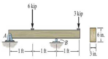
Prob. F12-3
Expert Solution & Answer
Want to see the full answer?
Check out a sample textbook solution
Students have asked these similar questions
F12-7. Two identical 20-mm-thick plates are bolted to the
top and bottom flange to form the built-up beam. If the
beam is subjected to a shear force of V = 300 kN, determine
the maximum spacing s of the bolts to the nearest mm if
cach bolt has a shear strength of 30 kN.
-200 mm
20 mm
10 mm
300 mm
ho mm
"20 mm
F12-6. The two identical boards are bolted together to
form the beam. Determine the maximum spacing s of the
bolts to the nearest mm if each bolt has a shear strength of
15 kN The beam is subjected to a shear force of V = 50 kN.
100 mm
100 mm
300 mm
F12-9. The boards are bolted together to form the built-up
beam. If the beamis subjected to ashear farce of V = 75 kN,
determine the allowable maximum spacing of the bolts to
the nearest multiples of 5 mm. Each bolt has a shear strength
of 30 kN.
25 mm
12 mm
12 mm
100 mm
e mm
Koo mm
Chapter 12 Solutions
Statics and Mechanics of Materials, Student Value Edition (5th Edition)
Ch. 12.2 - In each case, calculate the value of Q and t that...Ch. 12.2 - If the beam is subjected to a shear force of V =...Ch. 12.2 - Prob. 2FPCh. 12.2 - Determine the absolute maximum shear stress in the...Ch. 12.2 - If the beam is subjected to a shear force of V =...Ch. 12.2 - If the beam is made from four plates and subjected...Ch. 12.2 - If the wide-flange beam is subjected to a shear of...Ch. 12.2 - If the wide-flange beam is subjected to a shear of...Ch. 12.2 - If the wide-flange beam is subjected to a shear of...Ch. 12.2 - If the beam is subjected to a shear of V = 30kN,...
Ch. 12.2 - If the wide-flange beam is subjected to a shear of...Ch. 12.2 - The wood beam has an allowable shear stress of...Ch. 12.2 - The shaft is supported by a thrust bearing at A...Ch. 12.2 - The shaft is supported by a thrust bearing at A...Ch. 12.2 - Determine the largest shear force V that the...Ch. 12.2 - If the applied shear force V = 18 kip, determine...Ch. 12.2 - The overhang beam is subjected to the uniform...Ch. 12.2 - The beam is made from a polymer and is subjected...Ch. 12.2 - Determine the maximum shear stress in the strut if...Ch. 12.2 - Determine the maximum shear force V that the strut...Ch. 12.2 - Prob. 15PCh. 12.2 - Plot the shear-stress distribution over the cross...Ch. 12.2 - Prob. 17PCh. 12.2 - If the wide-flange beam is subjected to a shear of...Ch. 12.2 - If the wide-flange beam is subjected to a shear of...Ch. 12.2 - Determine the length of the cantilevered beam so...Ch. 12.2 - If the beam is made from wood having an allowable...Ch. 12.2 - Determine the largest intensity w of the...Ch. 12.2 - If w = 800 lb/ft, determine the absolute maximum...Ch. 12.2 - Determine the shear stress at point B on the web...Ch. 12.2 - Determine the maximum shear stress acting at...Ch. 12.2 - Railroad tics must be designed to resist large...Ch. 12.2 - Prob. 27PCh. 12.2 - Prob. 28PCh. 12.2 - Determine the maximum shear stress in the T-beam...Ch. 12.2 - Determine the maximum shear stress in the T-beam...Ch. 12.2 - Prob. 31PCh. 12.3 - The two identical boards are bolted together to...Ch. 12.3 - Two identical 20-mm-thick plates are bolted to the...Ch. 12.3 - Prob. 8FPCh. 12.3 - Prob. 9FPCh. 12.3 - The beam is constructed from two boards fastened...Ch. 12.3 - The beam is constructed from two boards fastened...Ch. 12.3 - The beam is constructed from three boards. If it...Ch. 12.3 - The beam is constructed from three boards....Ch. 12.3 - Prob. 36PCh. 12.3 - The double T-beam is fabricated by welding the...Ch. 12.3 - The beam is constructed from three boards....Ch. 12.3 - A beam is constructed from three boards bolted...Ch. 12.3 - The simply supported beam is built up from three...Ch. 12.3 - Prob. 41PCh. 12.3 - Prob. 42PCh. 12.3 - Prob. 43PCh. 12.3 - The box beam is constructed from four boards that...Ch. 12.3 - The member consists of two plastic channel strips...Ch. 12.3 - The member consists of two plastic channel strips...Ch. 12.3 - Prob. 47PCh. 12.3 - Prob. 48PCh. 12 - The beam is fabricated from four boards nailed...Ch. 12 - Prob. 2RPCh. 12 - Prob. 3RPCh. 12 - Prob. 4RPCh. 12 - Prob. 5RPCh. 12 - Prob. 6RPCh. 12 - Prob. 7RPCh. 12 - The member consists of two triangular plastic...Ch. 12 - If the pipe is subjected to a shear of V = 15 kip,...
Knowledge Booster


Learn more about
Need a deep-dive on the concept behind this application? Look no further. Learn more about this topic, mechanical-engineering and related others by exploring similar questions and additional content below.Similar questions
- I1-50. Determine the maximum tensile and compressive bending stress in the beam if it is subjected to a moment of M = 6kN m. 12 mm 12 mm -12 mm 75 mm 250 mm H-12 mmarrow_forwardThe shaft is supported by a smooth thrust bearing at A and smooth journal bearing at C. If d = 3 in., determine the absolute maximum bending stress in the shaft.arrow_forward12-26. Determine the maximum shear stress acting in the fiberglass beam at the section where the internal shear force is maximum. 3 kNim 25 kNim -2 m- 100 mm 18 mm 150 mm 12 mm 100 mm 18 mmarrow_forward
- F7-2 P7-3 Determine the absolute maximum shear stress developed in the beam. 3kip 61h. F-3arrow_forwardIf the beam is subjected to a shear of V=30kN determine the web's shear stress at A and B. Indicate the shear-stress components on a volume element located at these points. Set w = 125 mm. Show that the neutral axis is located at y = 0.1747 m 0.1747 m from the bottom and INA = 0.2182(10-³) m4. 30 mm 250 mm 30 mm 200 mm W -25 mm V Barrow_forwardDetermine the internal normal force at section A if the rod is subjected to the external uniformly distributed loading along its length of 8 kN>m.arrow_forward
- If the wide-flange beam is subjected to a shear of V = 30 kN, determine the maximum shear stress in the beam. Set w = 200 mmarrow_forward7-25. Determine the maximum shear stress in the T-beam at section C. Show the result on a volume element at this point. 10 kN/m A |C 3 m -1.5 m--1.5 m-| 150 mm 150 mm |30 mm E - 30 mm Probs. 7-24/25arrow_forward*11-8. The simply supported beam is made of timber that has an allowable bending stress of ơallow = 8.4 MPa and an allowable shear stress of Tallow = 0.7 MPa. Determine its smallest dimensions to the nearest multiples of 5 mm if it is rectangular and has height-to-width ratio of 1.5. 200 kN/m A В -0.9 m- -0.9 m- 1,5 b B.arrow_forward
- The T-beam is subjected to a shear of V = 150 kN. Determine the amount of this force that is supported by the web B.arrow_forwardThe cantilever beam is loaded with uniformly distributed loads of w1 = 32 in kn/m and w2= 13 in kn/m and a concentrated load of P= 70 in kn. Determine the Maximum Shear developed in the beam in kn and make sure your sign is correct. HINGE P kn W1 kn/m W2 kn/m A 3m. 2m.- 4m. --2m--- R1arrow_forwardI1-61. If the beam is subjected to an internal moment of M - 3kN m, determine the resultant force of the bending stress distribution acting an the top vertical board A. 100 mm 5 mm 75 mm -75m 25 mmarrow_forward
arrow_back_ios
SEE MORE QUESTIONS
arrow_forward_ios
Recommended textbooks for you
 Elements Of ElectromagneticsMechanical EngineeringISBN:9780190698614Author:Sadiku, Matthew N. O.Publisher:Oxford University Press
 Mechanics of Materials (10th Edition)Mechanical EngineeringISBN:9780134319650Author:Russell C. HibbelerPublisher:PEARSON
 Thermodynamics: An Engineering ApproachMechanical EngineeringISBN:9781259822674Author:Yunus A. Cengel Dr., Michael A. BolesPublisher:McGraw-Hill Education
 Control Systems EngineeringMechanical EngineeringISBN:9781118170519Author:Norman S. NisePublisher:WILEY
 Mechanics of Materials (MindTap Course List)Mechanical EngineeringISBN:9781337093347Author:Barry J. Goodno, James M. GerePublisher:Cengage Learning
 Engineering Mechanics: StaticsMechanical EngineeringISBN:9781118807330Author:James L. Meriam, L. G. Kraige, J. N. BoltonPublisher:WILEY
Elements Of Electromagnetics
Mechanical Engineering
ISBN:9780190698614
Author:Sadiku, Matthew N. O.
Publisher:Oxford University Press
Mechanics of Materials (10th Edition)
Mechanical Engineering
ISBN:9780134319650
Author:Russell C. Hibbeler
Publisher:PEARSON
Thermodynamics: An Engineering Approach
Mechanical Engineering
ISBN:9781259822674
Author:Yunus A. Cengel Dr., Michael A. Boles
Publisher:McGraw-Hill Education
Control Systems Engineering
Mechanical Engineering
ISBN:9781118170519
Author:Norman S. Nise
Publisher:WILEY
Mechanics of Materials (MindTap Course List)
Mechanical Engineering
ISBN:9781337093347
Author:Barry J. Goodno, James M. Gere
Publisher:Cengage Learning
Engineering Mechanics: Statics
Mechanical Engineering
ISBN:9781118807330
Author:James L. Meriam, L. G. Kraige, J. N. Bolton
Publisher:WILEY
Understanding Torsion; Author: The Efficient Engineer;https://www.youtube.com/watch?v=1YTKedLQOa0;License: Standard YouTube License, CC-BY