
EBK STATICS AND MECHANICS OF MATERIALS
5th Edition
ISBN: 8220102955295
Author: HIBBELER
Publisher: PEARSON
expand_more
expand_more
format_list_bulleted
Videos
Textbook Question
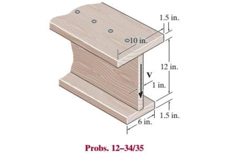
Chapter 12.3, Problem 35P
The beam is constructed from three boards. Determine the maximum shear V that it can support if the allowable shear stress for the wood is τallow = 400 psi. What is the maximum allowable spacing s of the nails if each nail can resist a shear force of 400 lb?
Expert Solution & Answer
Want to see the full answer?
Check out a sample textbook solution
Students have asked these similar questions
The beam has a square cross section and is made of
wood having an allowable shear stress of Tallow=
1.4 ksi. If it is subjected to a shear of V= 1.5 kip,
determine the smallest dimension a of its sides.
Sketch the shear stress distribution acting across
the beam's cross section.
Hint: Construct the stress distribution in 2D similar
to in-class examples, rather than isometrically
similar to the textbook examples for clarity.
V = 1.5 kip
The box beam is constructed from four boards that are fastened together using nails spaced along the beam every 2 in. If each nail can resist a shear force of 50 lb, determine the largest force P that can be applied to the beam without causing failure of the nails.
The boards are bolted together to form the built-up beam. If the beam is subjected to a shear force of V = 15 kip, determine the maximum spacing s of the bolts to the nearest 1 8 in. if each bolt has a shear strength of 6 kip.
Chapter 12 Solutions
EBK STATICS AND MECHANICS OF MATERIALS
Ch. 12.2 - In each case, calculate the value of Q and t that...Ch. 12.2 - If the beam is subjected to a shear force of V =...Ch. 12.2 - Prob. 2FPCh. 12.2 - Determine the absolute maximum shear stress in the...Ch. 12.2 - If the beam is subjected to a shear force of V =...Ch. 12.2 - If the beam is made from four plates and subjected...Ch. 12.2 - If the wide-flange beam is subjected to a shear of...Ch. 12.2 - If the wide-flange beam is subjected to a shear of...Ch. 12.2 - If the wide-flange beam is subjected to a shear of...Ch. 12.2 - If the beam is subjected to a shear of V = 30kN,...
Ch. 12.2 - If the wide-flange beam is subjected to a shear of...Ch. 12.2 - The wood beam has an allowable shear stress of...Ch. 12.2 - The shaft is supported by a thrust bearing at A...Ch. 12.2 - The shaft is supported by a thrust bearing at A...Ch. 12.2 - Determine the largest shear force V that the...Ch. 12.2 - If the applied shear force V = 18 kip, determine...Ch. 12.2 - The overhang beam is subjected to the uniform...Ch. 12.2 - The beam is made from a polymer and is subjected...Ch. 12.2 - Determine the maximum shear stress in the strut if...Ch. 12.2 - Determine the maximum shear force V that the strut...Ch. 12.2 - Prob. 15PCh. 12.2 - Plot the shear-stress distribution over the cross...Ch. 12.2 - Prob. 17PCh. 12.2 - If the wide-flange beam is subjected to a shear of...Ch. 12.2 - If the wide-flange beam is subjected to a shear of...Ch. 12.2 - Determine the length of the cantilevered beam so...Ch. 12.2 - If the beam is made from wood having an allowable...Ch. 12.2 - Determine the largest intensity w of the...Ch. 12.2 - If w = 800 lb/ft, determine the absolute maximum...Ch. 12.2 - Determine the shear stress at point B on the web...Ch. 12.2 - Determine the maximum shear stress acting at...Ch. 12.2 - Railroad tics must be designed to resist large...Ch. 12.2 - Prob. 27PCh. 12.2 - Prob. 28PCh. 12.2 - Determine the maximum shear stress in the T-beam...Ch. 12.2 - Determine the maximum shear stress in the T-beam...Ch. 12.2 - Prob. 31PCh. 12.3 - The two identical boards are bolted together to...Ch. 12.3 - Two identical 20-mm-thick plates are bolted to the...Ch. 12.3 - Prob. 8FPCh. 12.3 - Prob. 9FPCh. 12.3 - The beam is constructed from two boards fastened...Ch. 12.3 - The beam is constructed from two boards fastened...Ch. 12.3 - The beam is constructed from three boards. If it...Ch. 12.3 - The beam is constructed from three boards....Ch. 12.3 - Prob. 36PCh. 12.3 - The double T-beam is fabricated by welding the...Ch. 12.3 - The beam is constructed from three boards....Ch. 12.3 - A beam is constructed from three boards bolted...Ch. 12.3 - The simply supported beam is built up from three...Ch. 12.3 - Prob. 41PCh. 12.3 - Prob. 42PCh. 12.3 - Prob. 43PCh. 12.3 - The box beam is constructed from four boards that...Ch. 12.3 - The member consists of two plastic channel strips...Ch. 12.3 - The member consists of two plastic channel strips...Ch. 12.3 - Prob. 47PCh. 12.3 - Prob. 48PCh. 12 - The beam is fabricated from four boards nailed...Ch. 12 - Prob. 2RPCh. 12 - Prob. 3RPCh. 12 - Prob. 4RPCh. 12 - Prob. 5RPCh. 12 - Prob. 6RPCh. 12 - Prob. 7RPCh. 12 - The member consists of two triangular plastic...Ch. 12 - If the pipe is subjected to a shear of V = 15 kip,...
Knowledge Booster


Learn more about
Need a deep-dive on the concept behind this application? Look no further. Learn more about this topic, mechanical-engineering and related others by exploring similar questions and additional content below.Similar questions
- The box beam is constructed from four boards that are fastened together using nails spaced along the beam every 2 in. If a force P = 2 kip is applied to the beam, determine the shear force resisted by each nail at A and B.arrow_forwardPlease help mearrow_forward20 mm 20 mm 4. The simply supported beam on the right is built up from three boards by nailing them together as shown. If P = 12 kN, determine the maximum allowable spacing s of the nails to support the load, if each nail can resist a shear force of 1.5 kN. 1 m m B 100 mm 25 mm- 25 mm 200 mm 25 mmarrow_forward
- Determine the average shear stress developed in the nails within region AB of the beam. The nails are located on each side of the beam and are space 100 mm apart. Each nail has a diameter of 4 mm. Take P = 2kN. = Hint: Think carefully about the number of nails transferring shear stress from board-to-board. 2 kN/m A B -1.5 m 1.5 m 100 mm + 20 mm 40 mm 200 mm 20 mm 200 mmarrow_forwardQ1) For the beam loaded as shown, find the magnitude and the location of the maximum shearing stress due to the shearing force. skN 80 2 kN in 100 60 4•M36KN.m R = R = 17KN 4in 6im 4in - +120mmarrow_forwardTwo identical 20-mm-thick plates are bolted to the top and bottom flange to form the built-up beam. If the beam is subjected to a shear force of V = 300 kN, determine the maximum spacing s of the bolts to the nearest mm if eachbolt has a shear strength of 30 kN.arrow_forward
- The beam is constructed from two boards fastened together at the top and bottom with three rows of nails spaced every 8 in. If an internal shear force of V = 800 lb is applied to the boards, determine the shear force resisted by each nail.arrow_forwardDetermine the required diameter of the pins at A and B if the allowable shear stress for the material is tallow = 100 MPa. Both pins are subjected to double shear.arrow_forwardDetermine the required diameter of the pins at A and B to the nearest 116 in. if the allowable shear stress for the material is tallow = 6 ksi. Pin A is subjected to double shear, whereas pin B is subjected to single shear.arrow_forward
- The rows of staples AB contained in the stapler is glued together so that the maximum shear stress the glue can withstand is 12 psi. Determine the maximum force F that must be placed on the plunger in order to shear off a staple from its row and allow it to exit undeformed through the groove at C. The outer dimensions are shown in the figure below. The thickness of the staple is 0.05 in. Assume all the other parts are rigid.arrow_forwardThe H-beam is subjected to a shear of V = 80 kN. Sketch the shear-stress distribution acting along with one of its side segments. Indicate all peak values.arrow_forwardIf the beam has a rectangular cross-section, then the shear-stress distribution will be parabolic. True or False?arrow_forward
arrow_back_ios
SEE MORE QUESTIONS
arrow_forward_ios
Recommended textbooks for you
 Elements Of ElectromagneticsMechanical EngineeringISBN:9780190698614Author:Sadiku, Matthew N. O.Publisher:Oxford University Press
 Mechanics of Materials (10th Edition)Mechanical EngineeringISBN:9780134319650Author:Russell C. HibbelerPublisher:PEARSON
 Thermodynamics: An Engineering ApproachMechanical EngineeringISBN:9781259822674Author:Yunus A. Cengel Dr., Michael A. BolesPublisher:McGraw-Hill Education
 Control Systems EngineeringMechanical EngineeringISBN:9781118170519Author:Norman S. NisePublisher:WILEY
 Mechanics of Materials (MindTap Course List)Mechanical EngineeringISBN:9781337093347Author:Barry J. Goodno, James M. GerePublisher:Cengage Learning
 Engineering Mechanics: StaticsMechanical EngineeringISBN:9781118807330Author:James L. Meriam, L. G. Kraige, J. N. BoltonPublisher:WILEY
Elements Of Electromagnetics
Mechanical Engineering
ISBN:9780190698614
Author:Sadiku, Matthew N. O.
Publisher:Oxford University Press
Mechanics of Materials (10th Edition)
Mechanical Engineering
ISBN:9780134319650
Author:Russell C. Hibbeler
Publisher:PEARSON
Thermodynamics: An Engineering Approach
Mechanical Engineering
ISBN:9781259822674
Author:Yunus A. Cengel Dr., Michael A. Boles
Publisher:McGraw-Hill Education
Control Systems Engineering
Mechanical Engineering
ISBN:9781118170519
Author:Norman S. Nise
Publisher:WILEY
Mechanics of Materials (MindTap Course List)
Mechanical Engineering
ISBN:9781337093347
Author:Barry J. Goodno, James M. Gere
Publisher:Cengage Learning
Engineering Mechanics: Statics
Mechanical Engineering
ISBN:9781118807330
Author:James L. Meriam, L. G. Kraige, J. N. Bolton
Publisher:WILEY
Mechanics of Materials Lecture: Beam Design; Author: UWMC Engineering;https://www.youtube.com/watch?v=-wVs5pvQPm4;License: Standard Youtube License