
EBK STATICS AND MECHANICS OF MATERIALS
5th Edition
ISBN: 8220102955295
Author: HIBBELER
Publisher: PEARSON
expand_more
expand_more
format_list_bulleted
Concept explainers
Videos
Textbook Question
Chapter 12.2, Problem 25P
Determine the maximum shear stress acting at section a-a of the cantilevered strut.
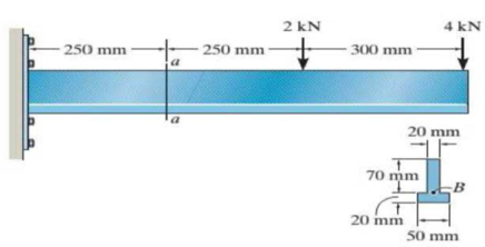
Probs. 12-24/25
Expert Solution & Answer
Want to see the full answer?
Check out a sample textbook solution
Students have asked these similar questions
8. If the allowable shear stress for each of the 10-mm-diameter steel pins at A, B, and C is
Ellow = 90 MPa, and the allowable normal stress for the 13-mm-diameter rod is Glow =
150 MPa, determine the largest intensity w of the uniform distributed load that can be
suspended from the beam.
1.2 m
B
0.9 g
Probs. 1-87/88
F7-2
P7-3 Determine the absolute maximum shear stress
developed in the beam.
3kip
61h.
F-3
F6-14. Determine the bending stress developed at corners
A and B. What is the orientation of the neutral axis?
5 so N-m
100 mm
150 mm
100 mm
150 mm
F6-14
Chapter 12 Solutions
EBK STATICS AND MECHANICS OF MATERIALS
Ch. 12.2 - In each case, calculate the value of Q and t that...Ch. 12.2 - If the beam is subjected to a shear force of V =...Ch. 12.2 - Prob. 2FPCh. 12.2 - Determine the absolute maximum shear stress in the...Ch. 12.2 - If the beam is subjected to a shear force of V =...Ch. 12.2 - If the beam is made from four plates and subjected...Ch. 12.2 - If the wide-flange beam is subjected to a shear of...Ch. 12.2 - If the wide-flange beam is subjected to a shear of...Ch. 12.2 - If the wide-flange beam is subjected to a shear of...Ch. 12.2 - If the beam is subjected to a shear of V = 30kN,...
Ch. 12.2 - If the wide-flange beam is subjected to a shear of...Ch. 12.2 - The wood beam has an allowable shear stress of...Ch. 12.2 - The shaft is supported by a thrust bearing at A...Ch. 12.2 - The shaft is supported by a thrust bearing at A...Ch. 12.2 - Determine the largest shear force V that the...Ch. 12.2 - If the applied shear force V = 18 kip, determine...Ch. 12.2 - The overhang beam is subjected to the uniform...Ch. 12.2 - The beam is made from a polymer and is subjected...Ch. 12.2 - Determine the maximum shear stress in the strut if...Ch. 12.2 - Determine the maximum shear force V that the strut...Ch. 12.2 - Prob. 15PCh. 12.2 - Plot the shear-stress distribution over the cross...Ch. 12.2 - Prob. 17PCh. 12.2 - If the wide-flange beam is subjected to a shear of...Ch. 12.2 - If the wide-flange beam is subjected to a shear of...Ch. 12.2 - Determine the length of the cantilevered beam so...Ch. 12.2 - If the beam is made from wood having an allowable...Ch. 12.2 - Determine the largest intensity w of the...Ch. 12.2 - If w = 800 lb/ft, determine the absolute maximum...Ch. 12.2 - Determine the shear stress at point B on the web...Ch. 12.2 - Determine the maximum shear stress acting at...Ch. 12.2 - Railroad tics must be designed to resist large...Ch. 12.2 - Prob. 27PCh. 12.2 - Prob. 28PCh. 12.2 - Determine the maximum shear stress in the T-beam...Ch. 12.2 - Determine the maximum shear stress in the T-beam...Ch. 12.2 - Prob. 31PCh. 12.3 - The two identical boards are bolted together to...Ch. 12.3 - Two identical 20-mm-thick plates are bolted to the...Ch. 12.3 - Prob. 8FPCh. 12.3 - Prob. 9FPCh. 12.3 - The beam is constructed from two boards fastened...Ch. 12.3 - The beam is constructed from two boards fastened...Ch. 12.3 - The beam is constructed from three boards. If it...Ch. 12.3 - The beam is constructed from three boards....Ch. 12.3 - Prob. 36PCh. 12.3 - The double T-beam is fabricated by welding the...Ch. 12.3 - The beam is constructed from three boards....Ch. 12.3 - A beam is constructed from three boards bolted...Ch. 12.3 - The simply supported beam is built up from three...Ch. 12.3 - Prob. 41PCh. 12.3 - Prob. 42PCh. 12.3 - Prob. 43PCh. 12.3 - The box beam is constructed from four boards that...Ch. 12.3 - The member consists of two plastic channel strips...Ch. 12.3 - The member consists of two plastic channel strips...Ch. 12.3 - Prob. 47PCh. 12.3 - Prob. 48PCh. 12 - The beam is fabricated from four boards nailed...Ch. 12 - Prob. 2RPCh. 12 - Prob. 3RPCh. 12 - Prob. 4RPCh. 12 - Prob. 5RPCh. 12 - Prob. 6RPCh. 12 - Prob. 7RPCh. 12 - The member consists of two triangular plastic...Ch. 12 - If the pipe is subjected to a shear of V = 15 kip,...
Knowledge Booster


Learn more about
Need a deep-dive on the concept behind this application? Look no further. Learn more about this topic, mechanical-engineering and related others by exploring similar questions and additional content below.Similar questions
- F6-15. Determine the maximum stress in the beam's cross section. 50 Ib-ft 6 in. F6-15arrow_forwardF7-7. Two klentical 20-mm thick plates are bollad to the top and bottom lange to form the buili-up heam. II the beam is subjected toa shear force of V = 300 KN, determine the allowable maximum spacing s of the boits to the nearest mm. Each bolt has a shcar strength of 30 RN. F7-9. The boards are boltod together to form the bull-up heam. Ir the beam is suhjactad to a shear force of V = 15 kip. determine the allowahle maximum spacing of the bolts le the nearst in. Each bolt has a shear strength of 6 kip. I in 05 in. 200 mm 3 in. 10 m 300 mm 10 mm 20 mm 7-9 FL7arrow_forwardDetermine the shear stress at point B on the web of the cantilevered strut at section a–a.arrow_forward
- *11-56. If the built-up beam is subjected to an internal moment of M = 75 kN - m, determine the maximum tensile and compressive stress acting in the beam. 150 mm 20 mm, so mm Tom150 mm 10 mm 300 mmarrow_forward11-58 The beam is subjected to a moment M. Determine the percentage of this moment that is resisted by the stresses acting on both the top and bottom boards of the beam. -90 mm 0 mm 20 mm 20 mm 20 mm 20 mm 100 mm 100 mm 20 mmarrow_forwardThe man has a mass of 100 kg and center of mass at G. If he holds himself in the position shown, determine the maximum tensile and compressive stress developed in the curved bar at section a–a. He is supported uniformly by twobars, each having a diameter of 25 mm. Assume the floor is smooth. Use the curved-beam formula to calculate the bending stress.arrow_forward
- 7-1. The shaft is supported by a smooth thrust bearing at B and a journal bearing at C. Determine the resultant internal loadings acting on the cross section at E. 1800 N 3600 Narrow_forwardF7-14. The frame supports the loading shown. The pin at A has a diameter of 50 mm. If it is subjected to double shear, determine the average shear stress in the pin. -2 m- -2 m- 60 kNarrow_forwardThe assembly consists of two sections of galvanized steel pipe connected together using a reducing coupling at B. The smaller pipe has an outer diameter of 0.75 in. and an inner diameter of 0.68 in., whereas the larger pipe has an outer diameter of 1 in. and an inner diameter of 0.86 in. If the pipe istightly secured to the wall at C, determine the maximum shear stress in each section of the pipe when the couple is applied to the handles of the wrench.arrow_forward
- 6-105. The member has a square cross section and is subjected to a resultant internal bending moment of M = 850 N m as shown. Determine the stress at cach corner and sketch the stress distribution produced by M. Set -30. 725 mm 125 mm 250 mm M-850 N-m Prob. 6-105arrow_forward1.6-8 A frame is made of a 2 m long vertical pipe CD and a brace AB formed from two flat bars (see figure). The frame is supported by bolted connections at points A and C, which are 2 m apart. The brace is fastened to the pipe at point B,arrow_forward11-86. If the overhanging beam is made of wood having the allowable tensile and compressive stresses of (m). = 4 MPa and (atm)e = 5'MPa, determine the maximum concentrated force P that can applied at the free end. -130mm- 5 mm 200 mm 25 mm 25 mmarrow_forward
arrow_back_ios
SEE MORE QUESTIONS
arrow_forward_ios
Recommended textbooks for you
 Elements Of ElectromagneticsMechanical EngineeringISBN:9780190698614Author:Sadiku, Matthew N. O.Publisher:Oxford University Press
 Mechanics of Materials (10th Edition)Mechanical EngineeringISBN:9780134319650Author:Russell C. HibbelerPublisher:PEARSON
 Thermodynamics: An Engineering ApproachMechanical EngineeringISBN:9781259822674Author:Yunus A. Cengel Dr., Michael A. BolesPublisher:McGraw-Hill Education
 Control Systems EngineeringMechanical EngineeringISBN:9781118170519Author:Norman S. NisePublisher:WILEY
 Mechanics of Materials (MindTap Course List)Mechanical EngineeringISBN:9781337093347Author:Barry J. Goodno, James M. GerePublisher:Cengage Learning
 Engineering Mechanics: StaticsMechanical EngineeringISBN:9781118807330Author:James L. Meriam, L. G. Kraige, J. N. BoltonPublisher:WILEY
Elements Of Electromagnetics
Mechanical Engineering
ISBN:9780190698614
Author:Sadiku, Matthew N. O.
Publisher:Oxford University Press
Mechanics of Materials (10th Edition)
Mechanical Engineering
ISBN:9780134319650
Author:Russell C. Hibbeler
Publisher:PEARSON
Thermodynamics: An Engineering Approach
Mechanical Engineering
ISBN:9781259822674
Author:Yunus A. Cengel Dr., Michael A. Boles
Publisher:McGraw-Hill Education
Control Systems Engineering
Mechanical Engineering
ISBN:9781118170519
Author:Norman S. Nise
Publisher:WILEY
Mechanics of Materials (MindTap Course List)
Mechanical Engineering
ISBN:9781337093347
Author:Barry J. Goodno, James M. Gere
Publisher:Cengage Learning
Engineering Mechanics: Statics
Mechanical Engineering
ISBN:9781118807330
Author:James L. Meriam, L. G. Kraige, J. N. Bolton
Publisher:WILEY
Everything About COMBINED LOADING in 10 Minutes! Mechanics of Materials; Author: Less Boring Lectures;https://www.youtube.com/watch?v=N-PlI900hSg;License: Standard youtube license