
CONNECT F/SHIGLEY'S MECH.ENGR.DESIGN>I<
10th Edition
ISBN: 9781260058499
Author: BUDYNAS
Publisher: INTER MCG
expand_more
expand_more
format_list_bulleted
Concept explainers
Videos
Textbook Question
Chapter 13, Problem 32P
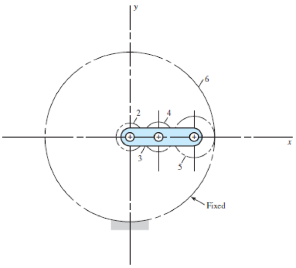
The 24T 6-pitch 20° pinion 2 shown in the figure rotates clockwise at 1000 rev/min and is driven at a power of 25 hp. Gears 4, 5, and 6 have 24, 36, and 144 teeth, respectively. What torque can arm 3 deliver to its output shaft? Draw free-body diagrams of the arm and of each gear and show all forces that act upon them.
Problem 13–32
Expert Solution & Answer

Trending nowThis is a popular solution!

Students have asked these similar questions
The figure shows a double-reduction helical gearset. Pinion 2 is the driver, and it receives a torque of 1200 Ibf • in from its shaft in the direction shown. Pinion 2 has a normal diametral pitch of 8 teeth/in, 14 teeth, and a normal pressure angle of 20° and is cut right-handed with a helix angle of 30°. The mating gear 3 on shaft b has 36 teeth. Gear 4, which is the driver for the second pair of gears in the train, has a normal diametral pitch of 3 teeth/in, 15 teeth, and a normal pressure angle of 20° and is cut left-handed with a helix angle of 15°. Mating gear S has 45 teeth. Find the magnitude and direction of the force exerted by the bearings C and D on shaft b if bearing C can take only a radial load while bearing D is mounted to take both radial and thrust loads.
A pair of helical gears transmit 15 KW power and the pinion is rotating at 1000 rpm. The helix angle is 0.50 radians and the normal pressure angle is 0.35 radians. The pitch diameter of the pinion is 70 mm and the pitch diameter of the gear is 210 mm. Determine the tangential, radial, and axial forces between the gear teeth.
The reducer input shaft shown in the figure is taperedIt transmits moment with the help of a gear wheel.On the spindle, Fa = 552 N, Fr = 457 N, Ft = 1960 Nfrom gear forces and belt mechanismincoming Fk = 2600 N radial force impact. The shaft rotates with n = 1090 rpm.Accept the shaft diameter in the A bearing as dA = 35 mm.Fixed ball bearing for Lh = 13500 hselect
Chapter 13 Solutions
CONNECT F/SHIGLEY'S MECH.ENGR.DESIGN>I<
Ch. 13 - A 17-tooth spur pinion has a diametral pitch of 8...Ch. 13 - A 15-tooth spur pinion has a module of 3 mm and...Ch. 13 - A spur gearset has a module of 6 mm and a velocity...Ch. 13 - A 21-tooth spur pinion mates with a 28-tooth gear....Ch. 13 - A 20 straight-tooth bevel pinion having 14 teeth...Ch. 13 - A parallel helical gearset uses a 20-tooth pinion...Ch. 13 - A parallel helical gearset consists of a 19-tooth...Ch. 13 - To avoid the problem of interference in a pair of...Ch. 13 - Prob. 9PCh. 13 - Prob. 10P
Ch. 13 - Prob. 11PCh. 13 - Prob. 12PCh. 13 - Prob. 13PCh. 13 - Prob. 14PCh. 13 - A parallel-shaft gearset consists of an 18-tooth...Ch. 13 - The double-reduction helical gearset shown in the...Ch. 13 - Shaft a in the figure rotates at 600 rev/min in...Ch. 13 - The mechanism train shown consists of an...Ch. 13 - The figure shows a gear train consisting of a pair...Ch. 13 - A compound reverted gear trains are to be designed...Ch. 13 - Prob. 21PCh. 13 - Prob. 22PCh. 13 - Prob. 23PCh. 13 - A gearbox is to be designed with a compound...Ch. 13 - The tooth numbers for the automotive differential...Ch. 13 - Prob. 26PCh. 13 - In the reverted planetary train illustrated, find...Ch. 13 - Prob. 28PCh. 13 - Tooth numbers for the gear train shown in the...Ch. 13 - The tooth numbers for the gear train illustrated...Ch. 13 - Shaft a in the figure has a power input of 75 kW...Ch. 13 - The 24T 6-pitch 20 pinion 2 shown in the figure...Ch. 13 - The gears shown in the figure have a module of 12...Ch. 13 - The figure shows a pair of shaft-mounted spur...Ch. 13 - Prob. 35PCh. 13 - Prob. 36PCh. 13 - A speed-reducer gearbox containing a compound...Ch. 13 - For the countershaft in Prob. 3-72, p. 152, assume...Ch. 13 - Prob. 39PCh. 13 - Prob. 40PCh. 13 - Prob. 41PCh. 13 - Prob. 42PCh. 13 - The figure shows a 16T 20 straight bevel pinion...Ch. 13 - The figure shows a 10 diametral pitch 18-tooth 20...Ch. 13 - Prob. 45PCh. 13 - The gears shown in the figure have a normal...Ch. 13 - Prob. 47PCh. 13 - Prob. 48PCh. 13 - Prob. 49PCh. 13 - The figure shows a double-reduction helical...Ch. 13 - A right-hand single-tooth hardened-steel (hardness...Ch. 13 - The hub diameter and projection for the gear of...Ch. 13 - A 2-tooth left-hand worm transmits 34 hp at 600...
Knowledge Booster


Learn more about
Need a deep-dive on the concept behind this application? Look no further. Learn more about this topic, mechanical-engineering and related others by exploring similar questions and additional content below.Similar questions
- A Coniflex, straight-tooth bevel gearset is supported on shafts with centerlines intersecting at a 90° angle. The gear is straddle mounted between closely positioned bearings, and the pinion overhangs its support bearing. The 15-tooth pinion rotates at 900 rpm, driving the 60-tooth gear, which has a di- ametral pitch of 6, pressure angle of 20°, and face width of 1.25 inches. The material for both gears is through-hardened Grade I steel with a hardness of BHN 300 (see Figure). It is desired to have a reliability of 90 percent, a design life of 10° cy- cles, and a governing safety factor of 2.5. Estimate the maximum horsepower that can be transmitted by this gear re- ducer while meeting all of the design specifications given.arrow_forwardpinion having 20 involute teeth of module pitch 6 mm rotates at 200 r.p.m. and transmits 1.5 kW to a gear wheel having 50 teeth. The addendum on both the wheels is 1/4 of the circular pitch. The angle of obliquity is 20°. Find (a) the length of the path of approach ; (b) the length of the arc of approach; (c) the normal force between the teeth at an instant where there is only pair of teeth in contact.arrow_forwardA truck equipped with a 50 HP engine uses a roller chain as the final drive to the rear axle. The driving sprocket runs at 225 rpm with a center distance of approximately 500 fpm. The transmission efficiency between the engine and the driving sprocket is 85%. 1.1 Determine the pitch and width of chain to be used. 1.2 Determine the number of teeth in each sprocket and the pitch diameters.arrow_forward
- The reducer input shaft shown in the figure is tapered It transmits moment with the help of a gear wheel. On the spindle, Fa = 552 N, Fr = 457 N, Ft = 1960 N from gear forces and belt mechanism incoming Fk = 2600 N radial force impact . The shaft rotates with n = 1090 rpm. Accept the shaft diameter in the A bearing as dA = 35 mm. Fixed ball suitable for Lh = 13500 h select bearing.arrow_forwardAn input shaft connected to the motor rotates at 1200 rpm, while the output speed must be 570 rpm. The contact force between the gears is transmitted through the pressure angle of 20°. The radial force is 321,90 kN. The material for both gear and pinion is 817M40.arrow_forwardA straight tooth spur pinion has a 19 tooth pinion rotating at a speed of 1640 rpm. The driven gear will be rotating at a speed of 480 rpm. If the module of the pinion is 2,5 mm and pressure angle is 25 degree; Evaluate the outer diameter (mm) of the gear. A) 158,125 B) 157,5 C) 160 D) 162,5 E) 160,625arrow_forward
- A steel shaft 800 mm long transmitting 15 kW at 400 r.p.m. is supported at two bearings at the twoends. A gear wheel having 80 teeth and 500 mm pitch circle diameter is mounted at 200 mm from theleft hand side bearing and receives power from a pinion meshing with it. The axis of pinion and gearlie in the horizontal plane. A pulley of 300 mm diameter is mounted at 200 mm from right hand sidebearing and is used for transmitting power by a belt. The belt drive is inclined at 30° to the vertical inthe forward direction. The belt lap angle is 180 degrees. The coefficient of friction between belt andpulley is 0.3. Design and sketch the arrangement of the shaft assuming the values of safe stresses as :τ = 55 MPa; σt= 80 MPa. Take torsion and bending factor 1.5 and 2 respectively.arrow_forwardThe double-reduction helical gearset shown in the figure is driven through shaft a at a speed of 700 rev/min. Gears 2 and 3 have a normal diametral pitch of 12 teeth/in, a 30° helix angle, and a normal pressure angle of 20°. The second pair of gears in the train, gears 4 and 5, have a normal diametral pitch of 8 teeth/in, a 25° helix angle, and a normal pressure angle of 20°. The tooth numbers are: N, = 12, N, = 48, N4 = 16, N, = 36. Find: (a) The directions of the thrust force exerted by each gear upon its shaft (b) The speed and direction of shaft c (c) The center distance between shaftsarrow_forwardProvide the complete step-by-step solution, given data, conversion of units, and sketch for this problem. A turbine at 30,000 rpm is used to drive a reduction gear delivering 3 hp at 3,000rpm. The gears are 20 degrees involute herringbone gears of 28 pitch and 2 1/8 ineffective width. The pinion has 20 teeth with a helix angle of 23 deg. Determine theload normal to the tooth surface. A. 20.4 lbs B. 24.4 lbs C. 28.4 lbs D. 32.4arrow_forward
- A simple gear train of 30 and 50 teeth for pinion and gear wheel respectively,is used to drive an electric wheelchair at a velocity that is double the maximum velocity of slip. The pinion has an equal addendum as the gear wheel, a module of 3 mm, and a pressure angle of 14.5o. The wheelchair has a maximum velocity of 5 m/s when its pinion rotates at 800 r.p.m. Calculate: 1.1. The magnitude of the velocity of slip of gears in mesh. (2)1.2. The angular speed of the gear wheel in rad/s. (4)1.3. The maximum length of a path of the approach in mm. (2)1.4. The length of a path of a recess in mm. (7)1.5. The addendum of the gears in mm. (7)1.6. The contact ratio.arrow_forwardsimple gear train of 30 and 50 teeth for pinion and gear wheel respectively, is used to drive an electric wheelchair at a velocity that is double the maximum velocity of slip. The pinion has an equal addendum as the gear wheel, a module of 3 mm, and a pressure angle of 14.5o. The wheelchair has a maximum velocity of 5 m/s when its pinion rotates at 800 r.p.m. Calculate: 1. The magnitude of the velocity of slip of gears in mesh.2. The angular speed of the gear wheel in rad/s.3. The maximum length of a path of the approach in mm.arrow_forwardA straight gear with module m = 5 mm and face width bw = 40 mm has center distance cd = 0.1875m. The pinion has 25 teeth, the speed is 1000 rpm, and pressure angle ᶲ = 200. Find the Hertzian contact stress at the pitch point when the gear transmits 10 kW. Neglect friction forces. The gear steel has modulus of elasticity E = 207 GPa and a Poisson’s ratio of 0.30.arrow_forward
arrow_back_ios
SEE MORE QUESTIONS
arrow_forward_ios
Recommended textbooks for you
 Elements Of ElectromagneticsMechanical EngineeringISBN:9780190698614Author:Sadiku, Matthew N. O.Publisher:Oxford University Press
 Mechanics of Materials (10th Edition)Mechanical EngineeringISBN:9780134319650Author:Russell C. HibbelerPublisher:PEARSON
 Thermodynamics: An Engineering ApproachMechanical EngineeringISBN:9781259822674Author:Yunus A. Cengel Dr., Michael A. BolesPublisher:McGraw-Hill Education
 Control Systems EngineeringMechanical EngineeringISBN:9781118170519Author:Norman S. NisePublisher:WILEY
 Mechanics of Materials (MindTap Course List)Mechanical EngineeringISBN:9781337093347Author:Barry J. Goodno, James M. GerePublisher:Cengage Learning
 Engineering Mechanics: StaticsMechanical EngineeringISBN:9781118807330Author:James L. Meriam, L. G. Kraige, J. N. BoltonPublisher:WILEY
Elements Of Electromagnetics
Mechanical Engineering
ISBN:9780190698614
Author:Sadiku, Matthew N. O.
Publisher:Oxford University Press
Mechanics of Materials (10th Edition)
Mechanical Engineering
ISBN:9780134319650
Author:Russell C. Hibbeler
Publisher:PEARSON
Thermodynamics: An Engineering Approach
Mechanical Engineering
ISBN:9781259822674
Author:Yunus A. Cengel Dr., Michael A. Boles
Publisher:McGraw-Hill Education
Control Systems Engineering
Mechanical Engineering
ISBN:9781118170519
Author:Norman S. Nise
Publisher:WILEY
Mechanics of Materials (MindTap Course List)
Mechanical Engineering
ISBN:9781337093347
Author:Barry J. Goodno, James M. Gere
Publisher:Cengage Learning
Engineering Mechanics: Statics
Mechanical Engineering
ISBN:9781118807330
Author:James L. Meriam, L. G. Kraige, J. N. Bolton
Publisher:WILEY
Power Transmission; Author: Terry Brown Mechanical Engineering;https://www.youtube.com/watch?v=YVm4LNVp1vA;License: Standard Youtube License