
Concept explainers
Videos
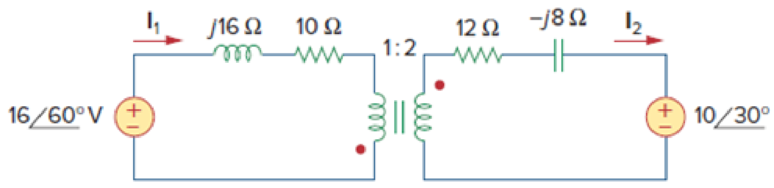
- (a) Find I1 and I2 in the circuit of Fig. 13.111 below.
- (b) Switch the dot on one of the windings. Find I1 and I2 again.
(a)
Calculate the value of currents
Answer to Problem 46P
The currents
Explanation of Solution
Given data:
Refer to Figure 13.111 in the textbook for the transformer circuit with given values.
Calculation:
In Figure 13.111, reflect the secondary circuit to the primary circuit. Consider the expression to find the input impedance
Write the Matlab code to find the input impedance.
n=2;
w=1;
R1=10;
L1=16;
ZL=12-i*8;
Z1=R1+i*(w*L1);
Zin= Z1+(ZL/n^2)
The Matlab output is given below.
Zin = 13 + 14i
From the Matlab output, the input impedance is,
Calculate the secondary side voltage source after reflection.
Substitute
The reduced circuit from Figure 13.111is drawn and it is shown in Figure 1.

From Figure 1, write the expression using Kirchhoff’s voltage law.
Substitute
Write the expression for the current
Substitute
Conclusion:
Thus, the currents
(b)
Calculate the value of currents
Answer to Problem 46P
The currents
Explanation of Solution
Calculation:
Consider that the dot in the secondary side is switched to the down side. Switching a dot will not affect the impedance
Calculate the secondary side voltage source after reflection when the dot is switched.
Substitute
The reduced circuit from Figure 13.111 is drawn and it is shown in Figure 2.
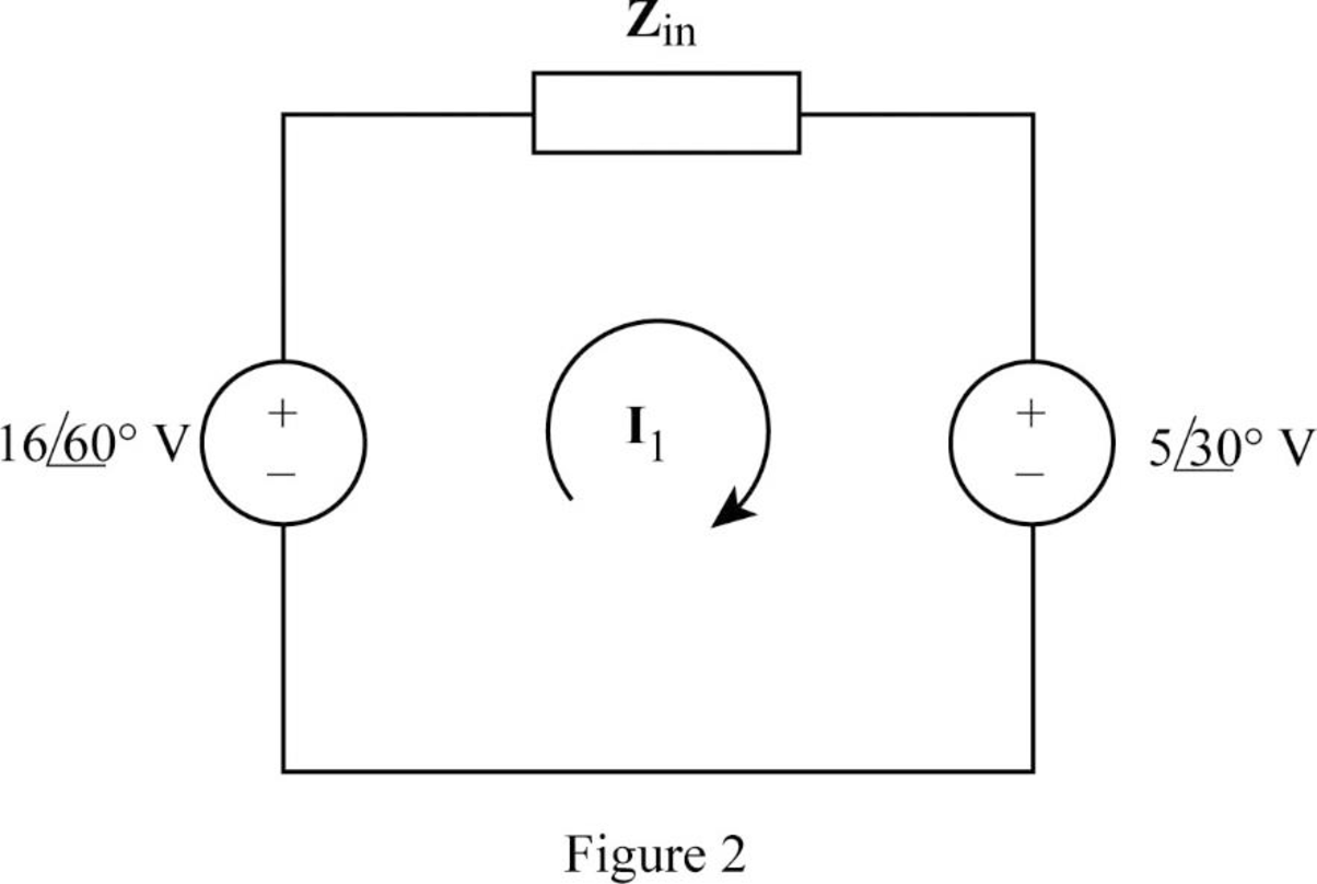
From Figure 1, write the expression using Kirchhoff’s voltage law.
Substitute
Write the expression for the current
Substitute
Conclusion:
Thus, the currents
Want to see more full solutions like this?
Chapter 13 Solutions
FUNDAMENTALS OF ELECTRONIC CIRCUITS LL


- A single phase practical transformer rated 100 kVA, 12470 volts primary, 600Vsecondary has a current and resistance of 0.101 of 220 kΩ. Determine thereactive power in kVAR.arrow_forwardThe maximum efficiency at Full-load and Unity power factor of a 1-phase, 25 kVA, 2000/1000V, 50Hz transformer is 98%. Determine its efficiency at 1/4th of full loadarrow_forwardA 15 KVA closet transformer lovated inside a building is used to step down the voltage for the buildinh. It is connected to a primary "Z800" V AC power source. The ratio of the number of primar windings to the number og secondary windings on the transforemer is 60 to 15. 1. what is the voltage provided to the building? 2. What is the amoung of current provided to the building? 3. If the building consymes 3200W of power, what is it's power factor? 4. What is the phase angle of the secondary power source in the building?arrow_forward
- 3. Calculate the full-load primary and secondary currents of a 5 kVA, 2400/120 V, transformer. Subject: Electrical Apparatus and Devicesarrow_forwardA 50-KVA, 13,800/208-V Delta-Star distribution transformer has a resistance of 1 percent and a reactance of 7 percent. Calculate this transformer's voltage regulation at full load and 0.8 PF lagging. A) 5.1% B) 3.1% C) 1.07% D) 2.25%.arrow_forward10. In a 25KVA, 2000 / 200 V power transformer, the iron and full load copper losses are 350W and 400W respectively. Calculate the efficiency at unity power factor at (i) full load and (ii) half load.arrow_forward
- A 2300/230 V distribution transformer is delivering a load of 50 kW to a certain part of a community. If the total wire impedance is .05 Ω, what power is actually dellvered? Ans. 47.64 kWarrow_forwardA three phase energy meter having a meter constant of 0.12rev/kWh isused with a potential transformer of ratio 22000/110V and a currenttransformer of ratio 500/5 amperes. When connected to a load of unitypower factor , the disc makes 40 revolutions in 61 seconds. If theinstrument readings are 110V and 5.25A, find the percentage error.arrow_forwardA transformer of 810 turns on the high side and 90 on the low side, is connected to a load of 8 + j3 on the low side. The transformer is connected to a 1080 volt network, Calculate: (a) Secondary voltage and current. b) Transformer ratio. c) Primary current. d) Load impedance referred to the primary. e) Power absorbed from the network.arrow_forward
- A 2MVA, 3-phase transformer, 33/11-kV, Y/Y, has a copper loss of 6 kW. The impedance drop at full-load is 7.5%. Calculate the primary voltage at rated load, 0.8 pf laggingarrow_forwardThe primary current to an ideal transformer rated at 3300/110 V is 5 A. Calculate: (a) the turns ratio, (b) the kVA rating, (c) the secondary current.arrow_forwardA 100/400 V, 2 kVA single-phase transformer has 5% impedance. If it is connected as a 500/400 V auto-transformer, determine its kVA rating and percentage impedance.arrow_forward
 Introductory Circuit Analysis (13th Edition)Electrical EngineeringISBN:9780133923605Author:Robert L. BoylestadPublisher:PEARSON
 Delmar's Standard Textbook Of ElectricityElectrical EngineeringISBN:9781337900348Author:Stephen L. HermanPublisher:Cengage Learning
 Programmable Logic ControllersElectrical EngineeringISBN:9780073373843Author:Frank D. PetruzellaPublisher:McGraw-Hill Education
 Fundamentals of Electric CircuitsElectrical EngineeringISBN:9780078028229Author:Charles K Alexander, Matthew SadikuPublisher:McGraw-Hill Education
 Electric Circuits. (11th Edition)Electrical EngineeringISBN:9780134746968Author:James W. Nilsson, Susan RiedelPublisher:PEARSON
 Engineering ElectromagneticsElectrical EngineeringISBN:9780078028151Author:Hayt, William H. (william Hart), Jr, BUCK, John A.Publisher:Mcgraw-hill Education,