
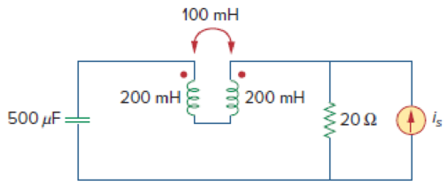
In the circuit of Fig. 13.93,
- (a) find the coupling coefficient,
- (b) calculate vo,
- (c) determine the energy stored in the coupled inductors at t = 2 s.
(a)
Calculate the coupling coefficient of the circuit in Figure 13.93.
Answer to Problem 24P
The coupling coefficient is
Explanation of Solution
Given data:
Refer to Figure 13.93 in the textbook for the circuit with coupled coils.
The value of
Calculation:
Consider the expression for the coefficient of coupling in the coupled coils.
Substitute 1 H for M, 4 H for
Conclusion:
Thus, the coupling coefficient is
(b)
Calculate the voltage
Answer to Problem 24P
The value of voltage
Explanation of Solution
Given data:
From Figure 13.93, the value of
Calculation:
Write the expression for the inductive reactance.
Write the expression for the capacitive reactance.
Substitute 4 H for
Substitute 2 H for
Substitute 1 H for
Substitute
Calculate load impedance
Modify the Figure 13.93 by transforming the time-domain circuit with coupled-coils to frequency domain of the circuit with coupled-coils. The frequency domain equivalent circuit is shown in Figure 1.
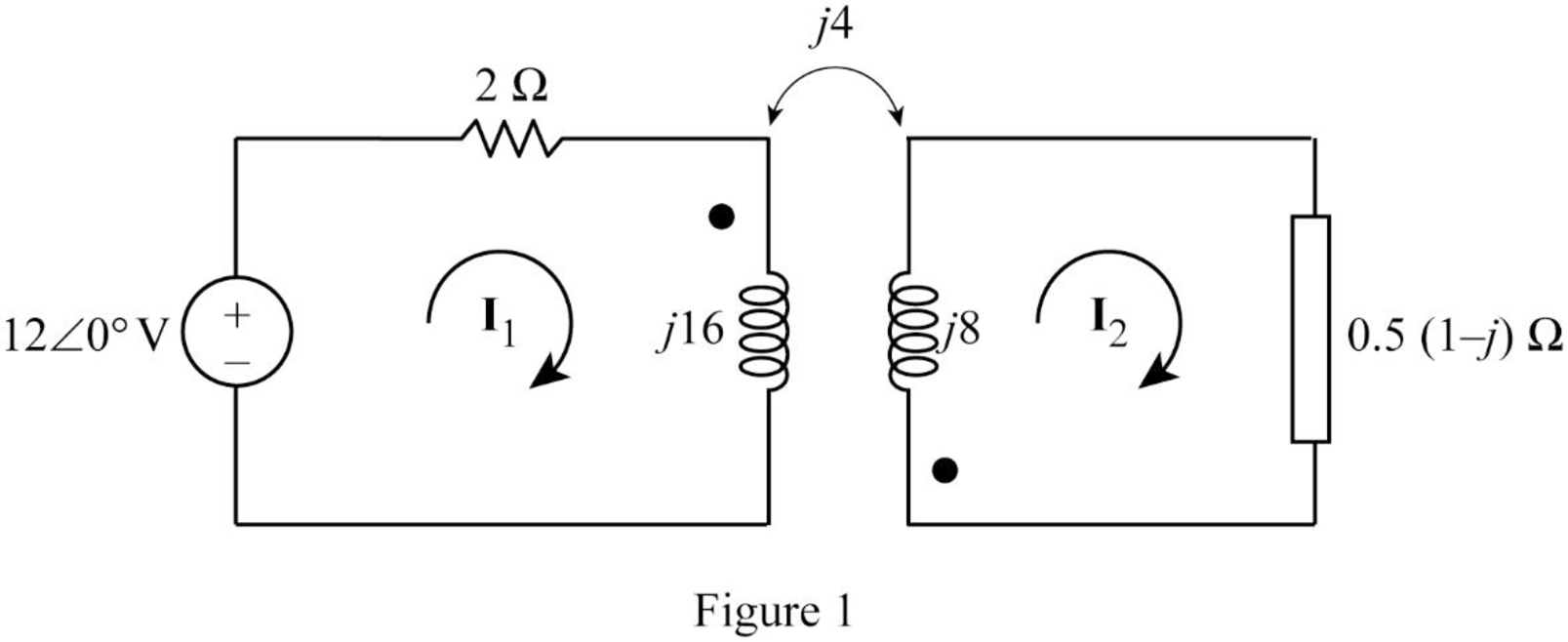
From Figure 1, consider that the loops 1 and 2 contain the currents
Apply Kirchhoff's voltage law to the loop 1 in Figure 1.
Apply Kirchhoff's voltage law to the loop 2 in Figure 1.
Write equations (3) and (4) in matrix form as follows.
Write the MATLAB code to solve the equation (5).
A = [(1+j*8) j*2;j*4 (0.5+j*7.5)];
B = [6; 0];
I = inv(A)*B
The output in command window:
I =
0.13036 - 0.84468i
-0.09912 + 0.44389i
From the MATLAB output, the currents
And
Write the expression for the voltage
Substitute
Convert the phasor form to time domain form.
Conclusion:
Thus, the value of voltage
(c)
Calculate the stored energy in the coupled coils at
Answer to Problem 24P
The energy stored in the coupled coils is
Explanation of Solution
Calculation:
From part (b), write the currents
Substitute 2 s for t in Equation (6).
Substitute 2 s for t in Equation (7).
Write the expression for the total energy stored in the coupled coils.
Substitute 4 H for
Conclusion:
Thus, the energy stored in the coupled coils is
Want to see more full solutions like this?
Chapter 13 Solutions
FUNDAMENTALS OF ELECTRONIC CIRCUITS LL
Additional Engineering Textbook Solutions
Microelectronics: Circuit Analysis and Design
ANALYSIS+DESIGN OF LINEAR CIRCUITS(LL)
Programmable Logic Controllers
Electric Circuits (10th Edition)
Electric machinery fundamentals
Electric Motors and Control Systems

- A resistor of 50 ohms, a 200mH inductor, and a 1.5 x 10⁻⁴ F capacitor are connected in parallel to a 120-volt, 60 cps source. Calculate: a) the total real, reactive, and apparent powers; b) power factor.arrow_forwardA coil of inductance 159.2 mH and resistance 40 ohms is connected in parallel with a 30 µF capacitor across a 240 V, 50 Hz supply.Calculate(a) Current in the coil and its phase angle (b) Current in the capacitor and its phase angle, (c) Supply current and its phase angle, (d) Circuit impedance, arrow_forwardFor the circuit in Fig. 13.18, determine the coupling coefficient and theenergy stored in the coupled inductors at t =1.5 s.arrow_forward
- Given a 115kV/13.2kV distribution transformer rated at 30MVA with an 8% nameplate impedance what is the full Load current in ampsarrow_forwardCalculate the equivalent impedance of a circuit where a coil of (5H, angle 53.2 Deg.) ohms is connected in parallel with a capacitive reactance of 6.25 ohms.arrow_forwardA coil having a resistance of 45 and an inductance of 0.4 H is connected in parallel with a capacitor having a capacitance of 20 μF across a 230-V, 50-Hz system. Calculate (a) the current taken from the supply (b) the power factor of the combination.arrow_forward
- A coil has a resistance of 4 and an inductance of 9.55 mH. Calculate (a) the reactance, (b) the impedance, and (c) the current taken from a 240V, 50 Hz supply. Determine also the phase angle between the supply voltage and currentarrow_forward34. A 33 kV, 50 Hz network has a capacitance to neutral of 1.0 µF per phase. Calculate the reactance of an arc suppression coil suitable for the system to avoid adverse effect of arching ground.arrow_forwardShow detailed solution. 21. The combined inductance of two coils connected in series is 0.6 H or 0.1 H depending on the relative directions of the currents in the coils. If one of the coils when isolated has a self inductance of 0.2 H, find the (a) mutual inductance (b) coefficient of coupling Answers: a. 0.125 H b. 0.72arrow_forward
- A coil has an inductance of 40 mH and negligible resistance. Calculate its inductive reactance and the resulting current if connected to (a) a 240V, 50 Hz supply, and (b) a 100V, 1 kHz supplyarrow_forward11. Two coupled coils have self-inductances L1 = 2 H and L2 = 0.5 H, and a coefficient of coupling K = 0.9. Determine the turns ratio N1/N2 of the two coils.arrow_forwardsingle coil 600 turns instrument transformer, operating in the step-down mode with a 40 percent tap, supplies a 5 kVA, 0.88 power factor inductive load. The input to the transformer is 3.3 kV, 50 Hz. Assume that leakage effects and minor losses in transformer are negligible. Determine the following : (0) Turn ratio; (ii) Load current(in Amp); (iii) Incoming line current(in Amp); (iv) Transformed current (in Amp); (v) Apparent power conducted(in kVA)and (vi) Apparent power transformed"arrow_forward
 Introductory Circuit Analysis (13th Edition)Electrical EngineeringISBN:9780133923605Author:Robert L. BoylestadPublisher:PEARSON
 Delmar's Standard Textbook Of ElectricityElectrical EngineeringISBN:9781337900348Author:Stephen L. HermanPublisher:Cengage Learning
 Programmable Logic ControllersElectrical EngineeringISBN:9780073373843Author:Frank D. PetruzellaPublisher:McGraw-Hill Education
 Fundamentals of Electric CircuitsElectrical EngineeringISBN:9780078028229Author:Charles K Alexander, Matthew SadikuPublisher:McGraw-Hill Education
 Electric Circuits. (11th Edition)Electrical EngineeringISBN:9780134746968Author:James W. Nilsson, Susan RiedelPublisher:PEARSON
 Engineering ElectromagneticsElectrical EngineeringISBN:9780078028151Author:Hayt, William H. (william Hart), Jr, BUCK, John A.Publisher:Mcgraw-hill Education,