
FUNDAMENTALS OF ELECTRONIC CIRCUITS LL
6th Edition
ISBN: 9781260842067
Author: Alexander
Publisher: MCG CUSTOM
expand_more
expand_more
format_list_bulleted
Concept explainers
Videos
Textbook Question
Chapter 13, Problem 74P
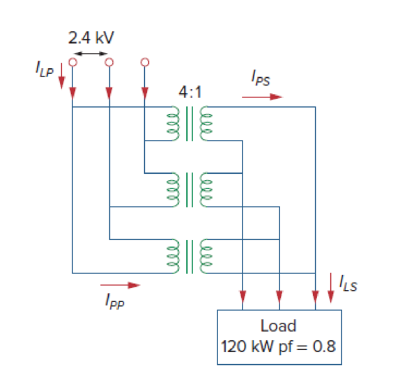
Consider the three-phase transformer shown in Fig. 13.136. The primary is fed by a three-phase source with line voltage of 2.4 kV rms, while the secondary supplies a three-phase 120-kW balanced load at pf of 0.8. Determine:
- (a) the type of transformer connections,
- (b) the values of ILS and IPS,
- (c) the values of ILP and IPP,
- (d) the kVA rating of each phase of the transformer.
Expert Solution & Answer
Want to see the full answer?
Check out a sample textbook solution
Students have asked these similar questions
In the ideal transformer circuit of Fig. 13.38, find and the complexpower supplied by the source.
A 2300/230 V distribution transformer is delivering a load of 50 kW to a certain
part of a community. If the total wire impedance is .05 Ω, what power is actually
dellvered? Ans. 47.64 kW
A 5,000-kVA, 3-phase transformer, 13.2/33-kV, A/Y, has a copper loss of 11 kW. The impedance drop at full-load is 7.5%. Calculate the primary voltage when a load of 4000 kW at 0.8 p.f. is delivered at 33 kv.
Chapter 13 Solutions
FUNDAMENTALS OF ELECTRONIC CIRCUITS LL
Ch. 13.2 - Determine the voltage Vo in the circuit of Fig....Ch. 13.2 - Determine the phasor currents I1 and I2 in the...Ch. 13.3 - Prob. 3PPCh. 13.4 - Find the input impedance of the circuit in Fig....Ch. 13.4 - For the linear transformer in Fig. 13.26(a), find...Ch. 13.4 - Solve the problem in Example 13.1 (see Fig. 13.9)...Ch. 13.5 - The primary current to an ideal transformer rated...Ch. 13.5 - In the ideal transformer circuit of Fig. 13.38,...Ch. 13.5 - Find Vo in the circuit of Fig. 13.40. Figure 13.40...Ch. 13.6 - Refer to Fig. 13.43. If the two-winding...
Ch. 13.6 - In the autotransformer circuit of Fig. 13.45, find...Ch. 13.7 - Prob. 12PPCh. 13.8 - Prob. 13PPCh. 13.9 - Refer to Fig. 13.61. Calculate the turns ratio...Ch. 13.9 - Calculate the turns ratio of an ideal transformer...Ch. 13.9 - In Example 13.17, if the eight 100-W bulbs are...Ch. 13 - Refer to the two magnetically coupled coils of...Ch. 13 - Prob. 2RQCh. 13 - Prob. 3RQCh. 13 - Prob. 4RQCh. 13 - The ideal transformer in Fig. 13.70(a) has N2/N1 =...Ch. 13 - Prob. 6RQCh. 13 - A three-winding transformer is connected as...Ch. 13 - Prob. 8RQCh. 13 - Prob. 9RQCh. 13 - Prob. 10RQCh. 13 - For the three coupled coils in Fig. 13.72,...Ch. 13 - Using Fig. 13.73, design a problem to help other...Ch. 13 - Two coils connected in series-aiding fashion have...Ch. 13 - (a) For the coupled coils in Fig. 13.74(a), show...Ch. 13 - Two coils are mutually coupled, with L1 = 50 mH,...Ch. 13 - Given the circuit shown in Fig. 13.75, determine...Ch. 13 - For the circuit in Fig. 13.76, find Vo. Figure...Ch. 13 - Find v(t) for the circuit in Fig. 13.77.Ch. 13 - Prob. 9PCh. 13 - Find vo in the circuit of Fig. 13.79. Figure 13.79...Ch. 13 - Use mesh analysis to find ix in Fig. 13.80, where...Ch. 13 - Determine the equivalent Leq in the circuit of...Ch. 13 - For the circuit in Fig. 13.82, determine the...Ch. 13 - Obtain the Thevenin equivalent circuit for the...Ch. 13 - Find the Norton equivalent for the circuit in Fig....Ch. 13 - Obtain the Norton equivalent at terminals a-b of...Ch. 13 - In the circuit of Fig. 13.86, ZL is a 15-mH...Ch. 13 - Find the Thevenin equivalent to the left of the...Ch. 13 - Determine an equivalent T-section that can be used...Ch. 13 - Determine currents I1, I2, and I3 in the circuit...Ch. 13 - Prob. 21PCh. 13 - Find current Io in the circuit of Fig. 13.91.Ch. 13 - Let is = 5 cos (100t) A. Calculate the voltage...Ch. 13 - In the circuit of Fig. 13.93, (a) find the...Ch. 13 - Prob. 25PCh. 13 - Find Io in the circuit of Fig. 13.95. Switch the...Ch. 13 - Find the average power delivered to the 50-...Ch. 13 - In the circuit of Fig. 13.97, find the value of X...Ch. 13 - Prob. 29PCh. 13 - (a) Find the input impedance of the circuit in...Ch. 13 - Using Fig. 13.100, design a problem to help other...Ch. 13 - Two linear transformers are cascaded as shown in...Ch. 13 - Determine the input impedance of the air-core...Ch. 13 - Using Fig. 13.103, design a problem to help other...Ch. 13 - Find currents I1, I2, and I3 in the circuit of...Ch. 13 - As done in Fig. 13.33, obtain the relationships...Ch. 13 - A 2402,400-V rms step-up ideal transformer...Ch. 13 - Design a problem to help other students better...Ch. 13 - A 1,200240-V rms transformer has impedance on the...Ch. 13 - The primary of an ideal transformer with a turns...Ch. 13 - Given I2 = 2 A, determine the value of Is in Fig....Ch. 13 - For the circuit in Fig. 13.107, determine the...Ch. 13 - Obtain V1 and V2 in the ideal transformer circuit...Ch. 13 - In the ideal transformer circuit of Fig. 13.109,...Ch. 13 - For the circuit in Fig. 13.110, find the value of...Ch. 13 - (a) Find I1 and I2 in the circuit of Fig. 13.111...Ch. 13 - Prob. 47PCh. 13 - Using Fig. 13.113, design a problem to help other...Ch. 13 - Find current ix in the ideal transformer circuit...Ch. 13 - Prob. 50PCh. 13 - Use the concept of reflected impedance to find the...Ch. 13 - For the circuit in Fig. 13.117, determine the...Ch. 13 - Refer to the network in Fig. 13.118. (a) Find n...Ch. 13 - A transformer is used to match an amplifier with...Ch. 13 - For the circuit in Fig. 13.120, calculate the...Ch. 13 - Find the power absorbed by the 100- resistor in...Ch. 13 - For the ideal transformer circuit of Fig. 13.122...Ch. 13 - Determine the average power absorbed by each...Ch. 13 - In the circuit of Fig. 13.124, let vs = 165...Ch. 13 - Refer to the circuit in Fig. 13.125 on the...Ch. 13 - For the circuit in Fig. 13.126, find Il, I2, and...Ch. 13 - For the network in Fig. 13.127, find: (a) the...Ch. 13 - Find the mesh currents in th circuit of Fig....Ch. 13 - For the circuit in Fig. 13.129. find the turns...Ch. 13 - Calculate the average power dissipated by the 20-...Ch. 13 - Design a problem to help other students better...Ch. 13 - An autotransformer with a 40 percent tap is...Ch. 13 - In the ideal autotransformer of Fig. 13.131,...Ch. 13 - In the circuit of Fig. 13.131, N1 = 190 turns and...Ch. 13 - In the ideal transformer circuit shown in Fig....Ch. 13 - When individuals travel, their electrical...Ch. 13 - In order to meet an emergency, three single-phase...Ch. 13 - Figure 13.135 on the next page shows a three-phase...Ch. 13 - Consider the three-phase transformer shown in Fig....Ch. 13 - A balanced three-phase transformer bank with the...Ch. 13 - Using Fig. 13.138, design a problem to help other...Ch. 13 - The three-phase system of a town distributes power...Ch. 13 - Use PSpice or MultiSim to determine the mesh...Ch. 13 - Use PSpice or MultiSim to find I1, I2, and I3 in...Ch. 13 - Prob. 80PCh. 13 - Use PSpice or MultiSim to find I1, I2, and I3 in...Ch. 13 - A stereo amplifier circuit with ail output...Ch. 13 - A transformer having 2,400 turns on the primary...Ch. 13 - A radio receiver has an input resistance of 300 ....Ch. 13 - A step-down power transformer with a turns ratio...Ch. 13 - A 240120-V rms power transformer is rated at 10...Ch. 13 - A 4-kVA, 2,400240-V rms transformer has 250 turns...Ch. 13 - A 25,000240-V rms distribution transformer has a...Ch. 13 - A 4,800-V rms transmission line feeds a...Ch. 13 - A four-winding transformer (Fig. 13.146) is often...Ch. 13 - A 440/110-V ideal transformer can be connected to...Ch. 13 - Ten bulbs in parallel are supplied by a 7,200120-V...
Knowledge Booster


Learn more about
Need a deep-dive on the concept behind this application? Look no further. Learn more about this topic, electrical-engineering and related others by exploring similar questions and additional content below.Similar questions
- An industrial plant is powered with a delta delta system, along with a transformer bank made up of single-phase transformers of 20KVA, 2300/230 V each. The bank supplies a 40 KVA load with a power factor of 0.7 (-). If a damaged transformer is removed for repair, calculate:a) The load in KVA that each transformer has.b) The nominal load of the transformer bank W.arrow_forwardA 6.9 kV/600 V, multi-tap, single-phase distribution transformer is connected to the far end of a distribution line for which the rear end voltage is maintained at 6.9 kV. The equivalent impedance of the transformer referred to low voltage side is 0.05 + j0.25 Ω per phase. The impedance of each line is 1 + j2 Ω. It is required to maintain a terminal voltage of 600 V when the line current of 300 A at 80% pf lagging is delivered to the load. What approximate percentage tapping is required in the primary side? Neglect the changes in impedance due to changes in turns ratio. A. 94 % B. 92 % C. 90 % D. 88 %arrow_forwardA 6.9 kV/600 V, multi-tap, single-phase distribution transformer is connected to the far end of a distribution line for which the rear end voltage is maintained at 6.9 kV. The equivalent impedance of the transformer referred to low voltage side is 0.05 + j0.25 Ω per phase. The impedance of each line is 1 + j2 Ω. It is required to maintain a terminal voltage of 600 V when the line current of 300 A at 80% pf lagging is delivered to the load. What approximate percentage tapping is required in the primary side? Neglect the changes in impedance due to changes in turns ratio.arrow_forward
- A network is composed of the utility having Ssc=500MVA, and an 800KVA transformer, rated at 20KV/410V (no load), whose voltage impedance is 5%, and whose load losses are 5400watts. the short circuit at the secondary of the transformer using the impedance method is: Select one: 45.8KA None of these 21.83KA 30.5KAarrow_forwardFor the linear transformer in Fig. 13.26(a), find the equivalentnetwork.arrow_forward1) A 600 V source feeds a 480 V load with a transformer Conventional 5000 VA, 480/120 V. Consider the ideal transformer. a) Calculate the apparent nominal power of the transformer in the connection as Autotransformer. b) Calculate the currents on the high voltage side and on the low voltage side in these conditions. c) Calculate the current in the common coil in the connection as Autotransformer.arrow_forward
- A network is composed of the utility having Ssc=250MVA, and an 2000KVA transformer, rated at 20KV/400V (no load), whose voltage impedance is 7%, and whose load losses are 15750watts. the short circuit at the secondary of the transformer using the impedance method is: a)27.01KA b)None of these c)25.8KA d)30KAarrow_forwardA 100/400 V, 2 kVA single-phase transformer has 5% impedance. If it is connected as a 500/400 V auto-transformer, determine its kVA rating and percentage impedance.arrow_forwardAn Electrical engineer is asked by a client to prepare a technical specification on specific items connected with a project. Hence, the engineer is requested to prepare the technical specification of the following: PROJECT: A Subdivision Development Lot AREA; 2 Hectares LOCATION: Brgy. Kanlurang Mayao, Lucna City Technical specification of fuse cutout Technical specification of transformerarrow_forward
- A 100kVA, 14/2.4kV, 60Hz single phase transformer is supplied through a line of 38+j140 ohm impedance. The transformer impedance referred to the secondary is 1+j4. A load of 90kW at 0.9 pf lagging is connected at the secondary terminal. Find the supply voltage (V1) if the load voltage is 2.3kV. Answer in whole number.arrow_forwardA 15 KVA closet transformer lovated inside a building is used to step down the voltage for the buildinh. It is connected to a primary "Z800" V AC power source. The ratio of the number of primar windings to the number og secondary windings on the transforemer is 60 to 15. 1. what is the voltage provided to the building? 2. What is the amoung of current provided to the building? 3. If the building consymes 3200W of power, what is it's power factor? 4. What is the phase angle of the secondary power source in the building?arrow_forwardCalculate the mesh currents in the circuit of Fig. 13.11.arrow_forward
arrow_back_ios
SEE MORE QUESTIONS
arrow_forward_ios
Recommended textbooks for you
 Introductory Circuit Analysis (13th Edition)Electrical EngineeringISBN:9780133923605Author:Robert L. BoylestadPublisher:PEARSON
 Delmar's Standard Textbook Of ElectricityElectrical EngineeringISBN:9781337900348Author:Stephen L. HermanPublisher:Cengage Learning
 Programmable Logic ControllersElectrical EngineeringISBN:9780073373843Author:Frank D. PetruzellaPublisher:McGraw-Hill Education
 Fundamentals of Electric CircuitsElectrical EngineeringISBN:9780078028229Author:Charles K Alexander, Matthew SadikuPublisher:McGraw-Hill Education
 Electric Circuits. (11th Edition)Electrical EngineeringISBN:9780134746968Author:James W. Nilsson, Susan RiedelPublisher:PEARSON
 Engineering ElectromagneticsElectrical EngineeringISBN:9780078028151Author:Hayt, William H. (william Hart), Jr, BUCK, John A.Publisher:Mcgraw-hill Education,
Introductory Circuit Analysis (13th Edition)
Electrical Engineering
ISBN:9780133923605
Author:Robert L. Boylestad
Publisher:PEARSON
Delmar's Standard Textbook Of Electricity
Electrical Engineering
ISBN:9781337900348
Author:Stephen L. Herman
Publisher:Cengage Learning
Programmable Logic Controllers
Electrical Engineering
ISBN:9780073373843
Author:Frank D. Petruzella
Publisher:McGraw-Hill Education
Fundamentals of Electric Circuits
Electrical Engineering
ISBN:9780078028229
Author:Charles K Alexander, Matthew Sadiku
Publisher:McGraw-Hill Education
Electric Circuits. (11th Edition)
Electrical Engineering
ISBN:9780134746968
Author:James W. Nilsson, Susan Riedel
Publisher:PEARSON
Engineering Electromagnetics
Electrical Engineering
ISBN:9780078028151
Author:Hayt, William H. (william Hart), Jr, BUCK, John A.
Publisher:Mcgraw-hill Education,
TRANSFORMERS - What They Are, How They Work, How Electricians Size Them; Author: Electrician U;https://www.youtube.com/watch?v=tXPy4OE7ApE;License: Standard Youtube License