SHIGLEY'S MECH.ENGR...(LL)-PKG.>CUSTOM<
10th Edition
ISBN: 9781260028379
Author: BUDYNAS
Publisher: MCG/CREATE
expand_more
expand_more
format_list_bulleted
Concept explainers
Videos
Textbook Question
Chapter 13, Problem 46P
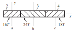
The gears shown in the figure have a normal diametral pitch of 5 teeth/in, a normal pressure angle of 20°, and a 30° helix angle. The transmitted load is 800 lbf. Gear 2 rotates clockwise about the y axis, as viewed from the positive y axis. Gear 3 is an idler. Find the forces exerted by gears 2 and 3 on their shafts.
Problem 13−46
Expert Solution & Answer

Trending nowThis is a popular solution!

Students have asked these similar questions
A pair of straight-tooth bevel gears (as shown in the figure above) are in mesh transmitting 35 hp at 1000 rpm (pinion speed). The gear rotates at 400 rpm. The gear system has a pitch of 6 and a 20-degree pressure angle. The face width is 2 inches and the pinion has 36 teeth. Determine the tangential, radial, and axial forces acting on the pinion
Shaft a in the figure has a power input of 75 kW at a speed of 1000 rev/min in the counterclockwise direction. The gears have a module of 5 mm and a 20° pressure angle. Gear 3 is an idler
(b) Find the torque T4c that gear 4 exerts on shaft c.
A gear train is composed of four helical gears with the three shaft axes in a single plane, as shown in the figure. The gears have a normal pressure angle of 20 and a 30 helix angle. Gear
is the driver, and is rotating counterclockwise as viewed from the top. Shaft b is an idler and the transmitted load from gear 2 to gear 3 is 500 Ibf. The gears on shaft b both have a normal diametral pitch of 7 teeth/in and have 54 and 14 teeth, respectively. Find the forces exerted by
gears 3 and 4 on shaft b
Chapter 13 Solutions
SHIGLEY'S MECH.ENGR...(LL)-PKG.>CUSTOM<
Ch. 13 - A 17-tooth spur pinion has a diametral pitch of 8...Ch. 13 - A 15-tooth spur pinion has a module of 3 mm and...Ch. 13 - A spur gearset has a module of 6 mm and a velocity...Ch. 13 - A 21-tooth spur pinion mates with a 28-tooth gear....Ch. 13 - A 20 straight-tooth bevel pinion having 14 teeth...Ch. 13 - A parallel helical gearset uses a 20-tooth pinion...Ch. 13 - A parallel helical gearset consists of a 19-tooth...Ch. 13 - To avoid the problem of interference in a pair of...Ch. 13 - Prob. 9PCh. 13 - Prob. 10P
Ch. 13 - Prob. 11PCh. 13 - Prob. 12PCh. 13 - Prob. 13PCh. 13 - Prob. 14PCh. 13 - A parallel-shaft gearset consists of an 18-tooth...Ch. 13 - The double-reduction helical gearset shown in the...Ch. 13 - Shaft a in the figure rotates at 600 rev/min in...Ch. 13 - The mechanism train shown consists of an...Ch. 13 - The figure shows a gear train consisting of a pair...Ch. 13 - A compound reverted gear trains are to be designed...Ch. 13 - Prob. 21PCh. 13 - Prob. 22PCh. 13 - Prob. 23PCh. 13 - A gearbox is to be designed with a compound...Ch. 13 - The tooth numbers for the automotive differential...Ch. 13 - Prob. 26PCh. 13 - In the reverted planetary train illustrated, find...Ch. 13 - Prob. 28PCh. 13 - Tooth numbers for the gear train shown in the...Ch. 13 - The tooth numbers for the gear train illustrated...Ch. 13 - Shaft a in the figure has a power input of 75 kW...Ch. 13 - The 24T 6-pitch 20 pinion 2 shown in the figure...Ch. 13 - The gears shown in the figure have a module of 12...Ch. 13 - The figure shows a pair of shaft-mounted spur...Ch. 13 - Prob. 35PCh. 13 - Prob. 36PCh. 13 - A speed-reducer gearbox containing a compound...Ch. 13 - For the countershaft in Prob. 3-72, p. 152, assume...Ch. 13 - Prob. 39PCh. 13 - Prob. 40PCh. 13 - Prob. 41PCh. 13 - Prob. 42PCh. 13 - The figure shows a 16T 20 straight bevel pinion...Ch. 13 - The figure shows a 10 diametral pitch 18-tooth 20...Ch. 13 - Prob. 45PCh. 13 - The gears shown in the figure have a normal...Ch. 13 - Prob. 47PCh. 13 - Prob. 48PCh. 13 - Prob. 49PCh. 13 - The figure shows a double-reduction helical...Ch. 13 - A right-hand single-tooth hardened-steel (hardness...Ch. 13 - The hub diameter and projection for the gear of...Ch. 13 - A 2-tooth left-hand worm transmits 34 hp at 600...
Knowledge Booster


Learn more about
Need a deep-dive on the concept behind this application? Look no further. Learn more about this topic, mechanical-engineering and related others by exploring similar questions and additional content below.Similar questions
- For a pair of standard gears, the module is m=2.5mm,pressure angle is α=20 0. ha*=1. c*=0.25. The teeth number on gear 1 is z1=22. The standard center distance is a=68.75mm. If the actual center distance is a’=69.75mm, find the working pressure angle α’=( )°arrow_forwardThe four helical gears shown in figure have a module in the normal plane of 4 mm and a pressure angle in the normal plane of 0.35 rad. The motor shaft rotates 550 rpm and transmits 20 kW. Other data are on the drawing. (a) What is the speed ratio between the motor (input) and output shafts? (b) Determine all force components that the 20-tooth pinion applies to the 50-tooth gear. Make a sketch showing these forces applied to the gear. (c) The same as part (b), except for the force components that the 50-tooth gear exerts on the 25- tooth pinion 100 50 teeth 200 125 25 teeth ψ = 0.35 rad right hand Motor 20 teeth ψ = 0.50 rad left hand 50 teeth Outputarrow_forward13–31 Shaft a in the figure has a power input of 75 kW at a speed of 1000 rev/min in the counterclockwise direction. The gears have a module of 5 mm and a 20° pressure angle. Gear 3 is an idler.(a) Find the force F3b that gear 3 exerts against shaft b.arrow_forward
- A gear train is composed of four helical gears with the tree shaft axes in a single plane, as shown in the figure. The gears have a normal pressure angle of 20° and a 30°helix angle. Gear 2 is the driver, and is rotating counterclockwise as viewed from the top. Shaft b is and idler and the transmitted load from gear 2 to gear 3 is 500 lbf. The gears on shaft b both have a normal diametral pitch of 7 teeth/in and have 54 and 14 teeth, respectively. Find the forces exerted by gears 3 and 4 on shaft b.arrow_forwardAn epicyclic gear shown in the figure, if gear A is fixed. Determine the speed reduction between the input and the output shafts If the input shaft rotates clockwise when viewed from the right end, what is the direction of rotation of the output shaft? BSs1 Cs0 A50 sarrow_forwardThe figure shows a double-reduction helical gearset. Pinion 2 is the driver, and it receives a torque of 1200 Ibf • in from its shaft in the direction shown. Pinion 2 has a normal diametral pitch of 8 teeth/in, 14 teeth, and a normal pressure angle of 20° and is cut right-handed with a helix angle of 30°. The mating gear 3 on shaft b has 36 teeth. Gear 4, which is the driver for the second pair of gears in the train, has a normal diametral pitch of 3 teeth/in, 15 teeth, and a normal pressure angle of 20° and is cut left-handed with a helix angle of 15°. Mating gear S has 45 teeth. Find the magnitude and direction of the force exerted by the bearings C and D on shaft b if bearing C can take only a radial load while bearing D is mounted to take both radial and thrust loads.arrow_forward
- A straight tooth spur pinion has a 19 tooth pinion rotating at a speed of 1640 rpm. The driven gear will be rotating at a speed of 480 rpm. If the module of the pinion is 2,5 mm and pressure angle is 25 degree; Evaluate the outer diameter (mm) of the gear. A) 158,125 B) 157,5 C) 160 D) 162,5 E) 160,625arrow_forwardProvide the complete step-by-step solution, given data, conversion of units, and sketch for this problem. A turbine at 30,000 rpm is used to drive a reduction gear delivering 3 hp at 3,000rpm. The gears are 20 degrees involute herringbone gears of 28 pitch and 2 1/8 ineffective width. The pinion has 20 teeth with a helix angle of 23 deg. Determine theload normal to the tooth surface. A. 20.4 lbs B. 24.4 lbs C. 28.4 lbs D. 32.4arrow_forwardFor a pair of standard gears, the module is m=2.5mm,pressure angle is α=20 0. ha*=1. c*=0.25. The teeth number on gear 1 is z1=22. The standard center distance is a=68.75mm. Calculate the contact ratio ε with the standard center distance a, 68.75mm. ε=( )arrow_forward
- A pair of helical gears transmit 15 KW power and the pinion is rotating at 1000 rpm. The helix angle is 0.50 radians and the normal pressure angle is 0.35 radians. The pitch diameter of the pinion is 70 mm and the pitch diameter of the gear is 210 mm. Determine the tangential, radial, and axial forces between the gear teeth.arrow_forwardThe top half of a compound Epicyclic gearset is shown in Figure, with input shaft I rotating at a constant speed of 700 rpm in a clockwise direction and generating 12 kW input power. The Annulus wheel A2 isform a compound wheel with gear O and connected to an auxiliary gear N on shaft X. . The Annulus A1 rotates in a counter-clockwise direction at a speed of 5,300 rpm. Calculate the following using this condition: The speed and direction of output shaft O (NO), shaft X (NX) and gear ratio (n). If Annulus wheel A1 is locked calculate the speed and direction of output shaft O (NO), shaft X (NX) and gear ratio (n). The braking torque (Tb) (magnitude and direction) that must be applied to Annulus wheel A1 to hold it stationary, assuming gear transmission efficiency is 90%. Number of gear teeth:P1 = 30 , A1 = 120P2 = 50 , A2 = 140N = 60 , O = 120arrow_forwardIn a gear set, a 36-tooth spur pinion drives a 60-tooth spur gear. The teeth of these gear are cast iron profile. The diametral pitch is 6-teeth/in, the face width si 0.5 inches, and the pressure angle is 20 degrees. Assume that the pinion transmits 10 hp at a speed of 2000 rpm. Find the tangential load in lbf Find the contact stress in kpsi, assuming CP=1960 psi.arrow_forward
arrow_back_ios
SEE MORE QUESTIONS
arrow_forward_ios
Recommended textbooks for you
 Elements Of ElectromagneticsMechanical EngineeringISBN:9780190698614Author:Sadiku, Matthew N. O.Publisher:Oxford University Press
 Mechanics of Materials (10th Edition)Mechanical EngineeringISBN:9780134319650Author:Russell C. HibbelerPublisher:PEARSON
 Thermodynamics: An Engineering ApproachMechanical EngineeringISBN:9781259822674Author:Yunus A. Cengel Dr., Michael A. BolesPublisher:McGraw-Hill Education
 Control Systems EngineeringMechanical EngineeringISBN:9781118170519Author:Norman S. NisePublisher:WILEY
 Mechanics of Materials (MindTap Course List)Mechanical EngineeringISBN:9781337093347Author:Barry J. Goodno, James M. GerePublisher:Cengage Learning
 Engineering Mechanics: StaticsMechanical EngineeringISBN:9781118807330Author:James L. Meriam, L. G. Kraige, J. N. BoltonPublisher:WILEY
Elements Of Electromagnetics
Mechanical Engineering
ISBN:9780190698614
Author:Sadiku, Matthew N. O.
Publisher:Oxford University Press
Mechanics of Materials (10th Edition)
Mechanical Engineering
ISBN:9780134319650
Author:Russell C. Hibbeler
Publisher:PEARSON
Thermodynamics: An Engineering Approach
Mechanical Engineering
ISBN:9781259822674
Author:Yunus A. Cengel Dr., Michael A. Boles
Publisher:McGraw-Hill Education
Control Systems Engineering
Mechanical Engineering
ISBN:9781118170519
Author:Norman S. Nise
Publisher:WILEY
Mechanics of Materials (MindTap Course List)
Mechanical Engineering
ISBN:9781337093347
Author:Barry J. Goodno, James M. Gere
Publisher:Cengage Learning
Engineering Mechanics: Statics
Mechanical Engineering
ISBN:9781118807330
Author:James L. Meriam, L. G. Kraige, J. N. Bolton
Publisher:WILEY
Power Transmission; Author: Terry Brown Mechanical Engineering;https://www.youtube.com/watch?v=YVm4LNVp1vA;License: Standard Youtube License