SHIGLEY'S MECH.ENGR...(LL)-PKG.>CUSTOM<
10th Edition
ISBN: 9781260028379
Author: BUDYNAS
Publisher: MCG/CREATE
expand_more
expand_more
format_list_bulleted
Concept explainers
Videos
Textbook Question
thumb_up100%
Chapter 13, Problem 17P
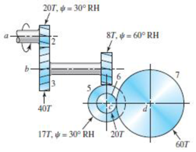
Shaft a in the figure rotates at 600 rev/min in the direction shown. Find the speed and direction of rotation of shaft d.
Problem 13-17
Expert Solution & Answer

Trending nowThis is a popular solution!

Students have asked these similar questions
13-32
The 247 6-pitch 20° pinion 2 shown in the figure rotates clockwise at 1000 rev/min and is driven at a power of 25 hp. Gears 4, 5, and 6 have 24, 36, and 144 teeth, respectively. What torque can arm 3 deliver to its output shaft? Draw free-body diagrams of the arm and of each gear and show all forces that act upon them.
In the Scottish Yoke mechanism in the figure, r = 63 cm, φ = 23 °, β = 116 ° and e = 34 cm are given. Accordingly, find the velocity of the S3 output since the angular velocity of the actuating limb is θ = 0.14 rad / s.
Partial scoring;
S3 50% in cm
The reducer input shaft shown in the figure is taperedIt transmits moment with the help of a gear wheel.On the spindle, Fa = 552 N, Fr = 457 N, Ft = 1960 Nfrom gear forces and belt mechanismincoming Fk = 2600 N radial force impact. The shaft rotates with n = 1090 rpm.Accept the shaft diameter in the A bearing as dA = 35 mm.Fixed ball bearing for Lh = 13500 hselect
Chapter 13 Solutions
SHIGLEY'S MECH.ENGR...(LL)-PKG.>CUSTOM<
Ch. 13 - A 17-tooth spur pinion has a diametral pitch of 8...Ch. 13 - A 15-tooth spur pinion has a module of 3 mm and...Ch. 13 - A spur gearset has a module of 6 mm and a velocity...Ch. 13 - A 21-tooth spur pinion mates with a 28-tooth gear....Ch. 13 - A 20 straight-tooth bevel pinion having 14 teeth...Ch. 13 - A parallel helical gearset uses a 20-tooth pinion...Ch. 13 - A parallel helical gearset consists of a 19-tooth...Ch. 13 - To avoid the problem of interference in a pair of...Ch. 13 - Prob. 9PCh. 13 - Prob. 10P
Ch. 13 - Prob. 11PCh. 13 - Prob. 12PCh. 13 - Prob. 13PCh. 13 - Prob. 14PCh. 13 - A parallel-shaft gearset consists of an 18-tooth...Ch. 13 - The double-reduction helical gearset shown in the...Ch. 13 - Shaft a in the figure rotates at 600 rev/min in...Ch. 13 - The mechanism train shown consists of an...Ch. 13 - The figure shows a gear train consisting of a pair...Ch. 13 - A compound reverted gear trains are to be designed...Ch. 13 - Prob. 21PCh. 13 - Prob. 22PCh. 13 - Prob. 23PCh. 13 - A gearbox is to be designed with a compound...Ch. 13 - The tooth numbers for the automotive differential...Ch. 13 - Prob. 26PCh. 13 - In the reverted planetary train illustrated, find...Ch. 13 - Prob. 28PCh. 13 - Tooth numbers for the gear train shown in the...Ch. 13 - The tooth numbers for the gear train illustrated...Ch. 13 - Shaft a in the figure has a power input of 75 kW...Ch. 13 - The 24T 6-pitch 20 pinion 2 shown in the figure...Ch. 13 - The gears shown in the figure have a module of 12...Ch. 13 - The figure shows a pair of shaft-mounted spur...Ch. 13 - Prob. 35PCh. 13 - Prob. 36PCh. 13 - A speed-reducer gearbox containing a compound...Ch. 13 - For the countershaft in Prob. 3-72, p. 152, assume...Ch. 13 - Prob. 39PCh. 13 - Prob. 40PCh. 13 - Prob. 41PCh. 13 - Prob. 42PCh. 13 - The figure shows a 16T 20 straight bevel pinion...Ch. 13 - The figure shows a 10 diametral pitch 18-tooth 20...Ch. 13 - Prob. 45PCh. 13 - The gears shown in the figure have a normal...Ch. 13 - Prob. 47PCh. 13 - Prob. 48PCh. 13 - Prob. 49PCh. 13 - The figure shows a double-reduction helical...Ch. 13 - A right-hand single-tooth hardened-steel (hardness...Ch. 13 - The hub diameter and projection for the gear of...Ch. 13 - A 2-tooth left-hand worm transmits 34 hp at 600...
Knowledge Booster


Learn more about
Need a deep-dive on the concept behind this application? Look no further. Learn more about this topic, mechanical-engineering and related others by exploring similar questions and additional content below.Similar questions
- pinion having 20 involute teeth of module pitch 6 mm rotates at 200 r.p.m. and transmits 1.5 kW to a gear wheel having 50 teeth. The addendum on both the wheels is 1/4 of the circular pitch. The angle of obliquity is 20°. Find (a) the length of the path of approach ; (b) the length of the arc of approach; (c) the normal force between the teeth at an instant where there is only pair of teeth in contact.arrow_forwardA 2 in diameter shaft uses a straight spline with seven splines and contact length of 1.5 in. Assuming it is designed to slide while under load, compute it torques transmission capacity at 100 rpm if h is 8% of that shaft diameter. Note S = 1200 psi.arrow_forwardA compound epicyclic gear is shown in Fig. for Q.2. C and D form acompound wheel which rotates freely on shaft G. The planet wheels B andE rotate on pins fixed in arms attached to shaft G. C and F have internalteeth: the others have external teeth with the following numbers: A, 40;B, 30; D, 50; E, 20. If A rotates at 500 rev/min and wheel F is fixed,find the speed of shaft G.arrow_forward
- The reducer input shaft shown in the figure is tapered It transmits moment with the help of a gear wheel. On the spindle, Fa = 552 N, Fr = 457 N, Ft = 1960 N from gear forces and belt mechanism incoming Fk = 2600 N radial force impact . The shaft rotates with n = 1090 rpm. Accept the shaft diameter in the A bearing as dA = 35 mm. Fixed ball suitable for Lh = 13500 h select bearing.arrow_forwardA synchronous belt drive system is used as a speed reducer. The input shaft rotates at 1000 rpm and has a 36-tooth sprocket with a pitch diameter of 3.609 in. The output shaft has a 72-tooth sprocket with a pitch diameter of 7.218 in. the center distance between the two shafts is 15.01 in. Determine the following for the belt drive: a. The velocity ratiob. The angular velocity of the output shaftc. The linear belt speedd. The belt wrap on the input and output sprocketse. The belt perimeter lengthf. Draw the schematic of the belt drive systemarrow_forwardThe double-reduction helical gearset shown in the figure is driven through shaft a at a speed of 700 rev/min. Gears 2 and 3 have a normal diametral pitch of 12 teeth/in, a 30° helix angle, and a normal pressure angle of 20°. The second pair of gears in the train, gears 4 and 5, have a normal diametral pitch of 8 teeth/in, a 25° helix angle, and a normal pressure angle of 20°. The tooth numbers are: N, = 12, N, = 48, N4 = 16, N, = 36. Find: (a) The directions of the thrust force exerted by each gear upon its shaft (b) The speed and direction of shaft c (c) The center distance between shaftsarrow_forward
- A cam, with a minimum radius of 25 mm, rotating clockwise at a uniform speed is to be designed to give a roller follower, at the end of a valve rod, motion described below : 1. To raise the valve through 50 mm during 120° rotation of the cam ; 2. To keep the valve fully raised through next 30°; 3. To lower the valve during next 120°; and 4. To keep the valve closed during rest of the revolution i.e. 90° ; The diameter of the roller is 20 mm and the diameter of the cam shaft is 25 mm. Draw the profile of the cam when (a) the line of stroke of the valve rod passes through the axis of the cam shaft, and (b) the line of the stroke is offset 15 mm from the axis of the cam shaft. The displacement of the valve, while being raised and lowered, is to take place with simple harmonic motion. Determine the maximum acceleration of the valve rod when the cam shaft rotates at 100 r.p.m. Draw the displacement, the velocity and the acceleration diagrams for one complete revolution of the cam.arrow_forwardA rack and pinion is a pair of gears that converts rotational motion into translation. As shown in the figure, a torque τ is applied to the shaft. The pinion rotates and causes the rack to translate. The mass moment of inertia of the pinion is I and the mass of the rack is m. Draw the free-body diagram and derive the differential equation of motionarrow_forwardA straight gear with module m = 5 mm and face width bw = 40 mm has center distance cd = 0.1875m. The pinion has 25 teeth, the speed is 1000 rpm, and pressure angle ᶲ = 200. Find the Hertzian contact stress at the pitch point when the gear transmits 10 kW. Neglect friction forces. The gear steel has modulus of elasticity E = 207 GPa and a Poisson’s ratio of 0.30.arrow_forward
- An epicyclic gear shown in figure below consists of ring gear, planet gear and sun gear. The ring gear has 72 internal teeth and sun gear has 32 external teeth. Planet gear meshes with both ring and sun gears and is carried on an arm which rotates about the centre of the ring gear at 20 r.p.m. If the gear A is fixed, Calculate the speed of plane gear.arrow_forwardA radial cam with a reciprocating follower is to be driven by a constant-speed motor at 150 rpm. The follower is to start from a dwell, accelerate to a uniform velocity of 25 in/s, maintain this velocity for 1.25 in of rise, decelerate to the top of the lift, return, and then dwell for 0.10 s. The total lift is to be 3.00 in. Determine the complete specifications of the displacement diagram.arrow_forwardTwo parallel shafts have an angular velocity ratio of 4 to 1 are connected by gears, the largest of which has 40 teeth. Find the number of teeth of smaller gear.arrow_forward
arrow_back_ios
SEE MORE QUESTIONS
arrow_forward_ios
Recommended textbooks for you
 Elements Of ElectromagneticsMechanical EngineeringISBN:9780190698614Author:Sadiku, Matthew N. O.Publisher:Oxford University Press
 Mechanics of Materials (10th Edition)Mechanical EngineeringISBN:9780134319650Author:Russell C. HibbelerPublisher:PEARSON
 Thermodynamics: An Engineering ApproachMechanical EngineeringISBN:9781259822674Author:Yunus A. Cengel Dr., Michael A. BolesPublisher:McGraw-Hill Education
 Control Systems EngineeringMechanical EngineeringISBN:9781118170519Author:Norman S. NisePublisher:WILEY
 Mechanics of Materials (MindTap Course List)Mechanical EngineeringISBN:9781337093347Author:Barry J. Goodno, James M. GerePublisher:Cengage Learning
 Engineering Mechanics: StaticsMechanical EngineeringISBN:9781118807330Author:James L. Meriam, L. G. Kraige, J. N. BoltonPublisher:WILEY
Elements Of Electromagnetics
Mechanical Engineering
ISBN:9780190698614
Author:Sadiku, Matthew N. O.
Publisher:Oxford University Press
Mechanics of Materials (10th Edition)
Mechanical Engineering
ISBN:9780134319650
Author:Russell C. Hibbeler
Publisher:PEARSON
Thermodynamics: An Engineering Approach
Mechanical Engineering
ISBN:9781259822674
Author:Yunus A. Cengel Dr., Michael A. Boles
Publisher:McGraw-Hill Education
Control Systems Engineering
Mechanical Engineering
ISBN:9781118170519
Author:Norman S. Nise
Publisher:WILEY
Mechanics of Materials (MindTap Course List)
Mechanical Engineering
ISBN:9781337093347
Author:Barry J. Goodno, James M. Gere
Publisher:Cengage Learning
Engineering Mechanics: Statics
Mechanical Engineering
ISBN:9781118807330
Author:James L. Meriam, L. G. Kraige, J. N. Bolton
Publisher:WILEY
Dynamics - Lesson 1: Introduction and Constant Acceleration Equations; Author: Jeff Hanson;https://www.youtube.com/watch?v=7aMiZ3b0Ieg;License: Standard YouTube License, CC-BY