
FUND. OF ELECTRIC CIRCUITS >CUSTOM<
null Edition
ISBN: 9781307184167
Author: Alexander
Publisher: MCG/CREATE
expand_more
expand_more
format_list_bulleted
Videos
Textbook Question
Chapter 13, Problem 75P
A balanced three-phase transformer bank with the Δ-Y connection depicted in Fig. 13.137 is used to step down line voltages from 4,500 V rms to 900 V rms. If the transformer feeds a 120-kVA load, find:
- (a) the turns ratio for the transformer,
- (b) the line currents at the primary and secondary sides.
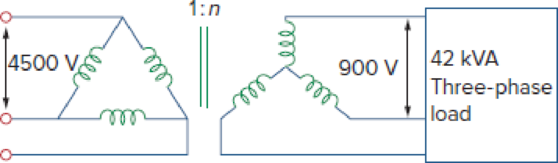
Figure 13.137
Expert Solution & Answer
Want to see the full answer?
Check out a sample textbook solution
Students have asked these similar questions
single coil 600 turns instrument transformer, operating in the step-down mode with a 40 percent tap, supplies a 5 kVA, 0.88 power factor inductive load. The input to the transformer is 3.3 kV, 50 Hz. Assume that leakage effects and minor losses in transformer are negligible. Determine the following : (0) Turn ratio; (ii) Load current(in Amp); (iii) Incoming line current(in Amp); (iv) Transformed current (in Amp); (v) Apparent power conducted(in kVA)and (vi) Apparent power transformed"
An Electrical engineer is asked by a client to prepare a technical specification on specific items connected with a project.
Hence, the engineer is requested to prepare the technical specification of the following:
PROJECT: A Subdivision Development
Lot AREA; 2 Hectares
LOCATION: Brgy. Kanlurang Mayao, Lucna City
Technical specification of fuse cutout
Technical specification of transformer
Q13) An ideal transformer connected to a 240V mains, supplies a 12V, 150W lamp. Calculate the Transformer turns ratio.
a.
45
b.
0.05
c.
50
d.
5
Chapter 13 Solutions
FUND. OF ELECTRIC CIRCUITS >CUSTOM<
Ch. 13.2 - Determine the voltage Vo in the circuit of Fig....Ch. 13.2 - Determine the phasor currents I1 and I2 in the...Ch. 13.3 - Prob. 3PPCh. 13.4 - Find the input impedance of the circuit in Fig....Ch. 13.4 - For the linear transformer in Fig. 13.26(a), find...Ch. 13.4 - Solve the problem in Example 13.1 (see Fig. 13.9)...Ch. 13.5 - The primary current to an ideal transformer rated...Ch. 13.5 - In the ideal transformer circuit of Fig. 13.38,...Ch. 13.5 - Find Vo in the circuit of Fig. 13.40. Figure 13.40...Ch. 13.6 - Refer to Fig. 13.43. If the two-winding...
Ch. 13.6 - In the autotransformer circuit of Fig. 13.45, find...Ch. 13.7 - Prob. 12PPCh. 13.8 - Prob. 13PPCh. 13.9 - Refer to Fig. 13.61. Calculate the turns ratio...Ch. 13.9 - Calculate the turns ratio of an ideal transformer...Ch. 13.9 - In Example 13.17, if the eight 100-W bulbs are...Ch. 13 - Refer to the two magnetically coupled coils of...Ch. 13 - Prob. 2RQCh. 13 - Prob. 3RQCh. 13 - Prob. 4RQCh. 13 - The ideal transformer in Fig. 13.70(a) has N2/N1 =...Ch. 13 - Prob. 6RQCh. 13 - A three-winding transformer is connected as...Ch. 13 - Prob. 8RQCh. 13 - Prob. 9RQCh. 13 - Prob. 10RQCh. 13 - For the three coupled coils in Fig. 13.72,...Ch. 13 - Using Fig. 13.73, design a problem to help other...Ch. 13 - Two coils connected in series-aiding fashion have...Ch. 13 - (a) For the coupled coils in Fig. 13.74(a), show...Ch. 13 - Two coils are mutually coupled, with L1 = 50 mH,...Ch. 13 - Given the circuit shown in Fig. 13.75, determine...Ch. 13 - For the circuit in Fig. 13.76, find Vo. Figure...Ch. 13 - Find v(t) for the circuit in Fig. 13.77.Ch. 13 - Prob. 9PCh. 13 - Find vo in the circuit of Fig. 13.79. Figure 13.79...Ch. 13 - Use mesh analysis to find ix in Fig. 13.80, where...Ch. 13 - Determine the equivalent Leq in the circuit of...Ch. 13 - For the circuit in Fig. 13.82, determine the...Ch. 13 - Obtain the Thevenin equivalent circuit for the...Ch. 13 - Find the Norton equivalent for the circuit in Fig....Ch. 13 - Obtain the Norton equivalent at terminals a-b of...Ch. 13 - In the circuit of Fig. 13.86, ZL is a 15-mH...Ch. 13 - Find the Thevenin equivalent to the left of the...Ch. 13 - Determine an equivalent T-section that can be used...Ch. 13 - Determine currents I1, I2, and I3 in the circuit...Ch. 13 - Prob. 21PCh. 13 - Find current Io in the circuit of Fig. 13.91.Ch. 13 - Let is = 5 cos (100t) A. Calculate the voltage...Ch. 13 - In the circuit of Fig. 13.93, (a) find the...Ch. 13 - Prob. 25PCh. 13 - Find Io in the circuit of Fig. 13.95. Switch the...Ch. 13 - Find the average power delivered to the 50-...Ch. 13 - In the circuit of Fig. 13.97, find the value of X...Ch. 13 - Prob. 29PCh. 13 - (a) Find the input impedance of the circuit in...Ch. 13 - Using Fig. 13.100, design a problem to help other...Ch. 13 - Two linear transformers are cascaded as shown in...Ch. 13 - Determine the input impedance of the air-core...Ch. 13 - Using Fig. 13.103, design a problem to help other...Ch. 13 - Find currents I1, I2, and I3 in the circuit of...Ch. 13 - As done in Fig. 13.33, obtain the relationships...Ch. 13 - A 2402,400-V rms step-up ideal transformer...Ch. 13 - Design a problem to help other students better...Ch. 13 - A 1,200240-V rms transformer has impedance on the...Ch. 13 - The primary of an ideal transformer with a turns...Ch. 13 - Given I2 = 2 A, determine the value of Is in Fig....Ch. 13 - For the circuit in Fig. 13.107, determine the...Ch. 13 - Obtain V1 and V2 in the ideal transformer circuit...Ch. 13 - In the ideal transformer circuit of Fig. 13.109,...Ch. 13 - For the circuit in Fig. 13.110, find the value of...Ch. 13 - (a) Find I1 and I2 in the circuit of Fig. 13.111...Ch. 13 - Prob. 47PCh. 13 - Using Fig. 13.113, design a problem to help other...Ch. 13 - Find current ix in the ideal transformer circuit...Ch. 13 - Prob. 50PCh. 13 - Use the concept of reflected impedance to find the...Ch. 13 - For the circuit in Fig. 13.117, determine the...Ch. 13 - Refer to the network in Fig. 13.118. (a) Find n...Ch. 13 - A transformer is used to match an amplifier with...Ch. 13 - For the circuit in Fig. 13.120, calculate the...Ch. 13 - Find the power absorbed by the 100- resistor in...Ch. 13 - For the ideal transformer circuit of Fig. 13.122...Ch. 13 - Determine the average power absorbed by each...Ch. 13 - In the circuit of Fig. 13.124, let vs = 165...Ch. 13 - Refer to the circuit in Fig. 13.125 on the...Ch. 13 - For the circuit in Fig. 13.126, find Il, I2, and...Ch. 13 - For the network in Fig. 13.127, find: (a) the...Ch. 13 - Find the mesh currents in th circuit of Fig....Ch. 13 - For the circuit in Fig. 13.129. find the turns...Ch. 13 - Calculate the average power dissipated by the 20-...Ch. 13 - Design a problem to help other students better...Ch. 13 - An autotransformer with a 40 percent tap is...Ch. 13 - In the ideal autotransformer of Fig. 13.131,...Ch. 13 - In the circuit of Fig. 13.131, N1 = 190 turns and...Ch. 13 - In the ideal transformer circuit shown in Fig....Ch. 13 - When individuals travel, their electrical...Ch. 13 - In order to meet an emergency, three single-phase...Ch. 13 - Figure 13.135 on the next page shows a three-phase...Ch. 13 - Consider the three-phase transformer shown in Fig....Ch. 13 - A balanced three-phase transformer bank with the...Ch. 13 - Using Fig. 13.138, design a problem to help other...Ch. 13 - The three-phase system of a town distributes power...Ch. 13 - Use PSpice or MultiSim to determine the mesh...Ch. 13 - Use PSpice or MultiSim to find I1, I2, and I3 in...Ch. 13 - Prob. 80PCh. 13 - Use PSpice or MultiSim to find I1, I2, and I3 in...Ch. 13 - A stereo amplifier circuit with ail output...Ch. 13 - A transformer having 2,400 turns on the primary...Ch. 13 - A radio receiver has an input resistance of 300 ....Ch. 13 - A step-down power transformer with a turns ratio...Ch. 13 - A 240120-V rms power transformer is rated at 10...Ch. 13 - A 4-kVA, 2,400240-V rms transformer has 250 turns...Ch. 13 - A 25,000240-V rms distribution transformer has a...Ch. 13 - A 4,800-V rms transmission line feeds a...Ch. 13 - A four-winding transformer (Fig. 13.146) is often...Ch. 13 - A 440/110-V ideal transformer can be connected to...Ch. 13 - Ten bulbs in parallel are supplied by a 7,200120-V...
Additional Engineering Textbook Solutions
Find more solutions based on key concepts
Design an ideal inverting op-amp circuit such that the voltage gain is Av=25 . The maximum current in any resis...
Microelectronics: Circuit Analysis and Design
Three point charges of equal magnitude q, that will yield a zero net electric field at the origin.
Engineering Electromagnetics
Does the severity of an electric shock increase ordecrease with eh of the following changes? a. A decrease in t...
Electric Motors and Control Systems
Find I0 and I1 in the circuit in Fig.P2.12.
Basic Engineering Circuit Analysis
Write the nodal equations for the network of Fig. 8.137 using the general approach. Find the nodal voltages usi...
Introductory Circuit Analysis (13th Edition)
Explain the main function of each of the following major components of a PLC: a. Processor module (CPU) b. I/O ...
Programmable Logic Controllers
Knowledge Booster


Learn more about
Need a deep-dive on the concept behind this application? Look no further. Learn more about this topic, electrical-engineering and related others by exploring similar questions and additional content below.Similar questions
- Given a 115kV/13.2kV distribution transformer rated at 30MVA with an 8% nameplate impedance what is the full Load current in ampsarrow_forward3. Calculate the full-load primary and secondary currents of a 5 kVA, 2400/120 V, transformer. Subject: Electrical Apparatus and Devicesarrow_forwardElectrical engineering A 375 kVA, 6600/400 V, 3-phase core type transformer has a total loss of 3700 watts on full load. The transformer tank is 1.25 m in height and 1 m × 0.5 m in plan. Design a suitable scheme for cooling tubes if the average temperature rise is to be limited to 35 °C. The diameter of the tube is 50 mm and are spaced 75 mm from each other. The average height of the tube is 1.05 m.arrow_forward
- "A single coil 800 turns instrument transformer, operating in the step-downs mode with a 25 percent tap, supplies a 10 kVA, 0.80 power factor lagging load. The input to the transformer is 6600 V, 50 Hz. Assume that leakage effects and minor losses in transformer are negligible. Determine the following : (i) Turn ratio; (ii) Load current(in Amp); (iii) Incoming line current(in Amp); (iv) Transformed current (in Amp); (v) Apparent power conducted(in kVA)and (vi) Apparent power transformed"arrow_forwardA 100-KVA, 20/5 KV transformer has an equivalent impedance of 10%. Calculate the impedance (in ohm/s)of the transformer referred to the 5 KV side.arrow_forward1) A 600 V source feeds a 480 V load with a transformer Conventional 5000 VA, 480/120 V. Consider the ideal transformer. a) Calculate the apparent nominal power of the transformer in the connection as Autotransformer. b) Calculate the currents on the high voltage side and on the low voltage side in these conditions. c) Calculate the current in the common coil in the connection as Autotransformer.arrow_forward
- Please Solve ASPS. A 100 kVA, 2000/400 V, 50 Hz, single phase shell type transformer has sandwitch coils. There are two full HIV coils, one full LV coil and two half LV colls. Calculate the value of leakage reactance referred to HV side if the other data given is, depth of HV coil = 4 cm depth of LV coil = 3.6 cm depth of duct between IIV and LV= 1.6 cm width of winding 12 cm length of mean turns = 150 cm HV winding turns = 200 Also calculate the per unit reactance.arrow_forwardA 5,000-kVA, 3-phase transformer, 13.2/33-kV, A/Y, has a copper loss of 11 kW. The impedance drop at full-load is 7.5%. Calculate the primary voltage when a load of 4000 kW at 0.8 p.f. is delivered at 33 kv.arrow_forwardF.a. In a step-up transformer having a 1 to 2 turn ratio, the 12-V secondary provides 5 A to the load. The primary current isA. 20 AB. 5 AC. 10 AD. 2.5 A F.b. Which one of the following voltages is typical of a value used by utilities for long-distance transmission of electrical power?A. 4800 VB. 345,000 VC. 240 VD. 120 Varrow_forward
- A 10kVA single phase transformer designed for 2000/400 V has the following constants, R1 = 5.5 ohms, R2 = 0.2 ohms; X1=12 ohms, X2=0.45 ohms. Calculate the approximate value of the secondary voltage at full load, 0.8 lagging, when the primary supply voltage is 2000V.arrow_forwardA transformer has 440 primary windings and 22 secondary windings. The potential difference across the primary coil is 100 V. The secondary coil is connected across a 125-ohm resistor. Find (a) secondary current (b) primary current. Hint: Use conservation of power. (c) effective load resistance of the SECONDARY COIL, which is connected across a 125 ohm resistor.arrow_forwardA 2300/230 V distribution transformer is delivering a load of 50 kW to a certain part of a community. If the total wire impedance is .05 Ω, what power is actually dellvered? Ans. 47.64 kWarrow_forward
arrow_back_ios
SEE MORE QUESTIONS
arrow_forward_ios
Recommended textbooks for you
 Introductory Circuit Analysis (13th Edition)Electrical EngineeringISBN:9780133923605Author:Robert L. BoylestadPublisher:PEARSON
 Delmar's Standard Textbook Of ElectricityElectrical EngineeringISBN:9781337900348Author:Stephen L. HermanPublisher:Cengage Learning
 Programmable Logic ControllersElectrical EngineeringISBN:9780073373843Author:Frank D. PetruzellaPublisher:McGraw-Hill Education
 Fundamentals of Electric CircuitsElectrical EngineeringISBN:9780078028229Author:Charles K Alexander, Matthew SadikuPublisher:McGraw-Hill Education
 Electric Circuits. (11th Edition)Electrical EngineeringISBN:9780134746968Author:James W. Nilsson, Susan RiedelPublisher:PEARSON
 Engineering ElectromagneticsElectrical EngineeringISBN:9780078028151Author:Hayt, William H. (william Hart), Jr, BUCK, John A.Publisher:Mcgraw-hill Education,
Introductory Circuit Analysis (13th Edition)
Electrical Engineering
ISBN:9780133923605
Author:Robert L. Boylestad
Publisher:PEARSON
Delmar's Standard Textbook Of Electricity
Electrical Engineering
ISBN:9781337900348
Author:Stephen L. Herman
Publisher:Cengage Learning
Programmable Logic Controllers
Electrical Engineering
ISBN:9780073373843
Author:Frank D. Petruzella
Publisher:McGraw-Hill Education
Fundamentals of Electric Circuits
Electrical Engineering
ISBN:9780078028229
Author:Charles K Alexander, Matthew Sadiku
Publisher:McGraw-Hill Education
Electric Circuits. (11th Edition)
Electrical Engineering
ISBN:9780134746968
Author:James W. Nilsson, Susan Riedel
Publisher:PEARSON
Engineering Electromagnetics
Electrical Engineering
ISBN:9780078028151
Author:Hayt, William H. (william Hart), Jr, BUCK, John A.
Publisher:Mcgraw-hill Education,
Mesh Current Problems in Circuit Analysis - Electrical Circuits Crash Course - Beginners Electronics; Author: Math and Science;https://www.youtube.com/watch?v=DYg8B-ElK0s;License: Standard Youtube License