Statics and Mechanics of Materials (5th Edition)
5th Edition
ISBN: 9780134382869
Author: HIBBELER
Publisher: PEARSON
expand_more
expand_more
format_list_bulleted
Concept explainers
Videos
Textbook Question
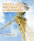
Chapter 13.2, Problem 4FP
Determine the magnitude of the load P that will cause a maximum normal stress of σmax = 30 ksi in the link along section a–a.
Expert Solution & Answer
Want to see the full answer?
Check out a sample textbook solution
Students have asked these similar questions
Determine the maximum compressive stress in the bracket at section a-a when the load P = 70 kN is applied at x = 0.
The pins on the frame at B and C each have a diameter of 0.25 in. If those pins are subjected to double shear, determine the factor of safety of each pin if the allowable stress for each pin is 12 ksi.
The post has a circular cross section of radius c. Determine the maximum radius e at which the load P can be applied so that no part of the post experiences a tensile stress. Neglect the weight of the post.
Chapter 13 Solutions
Statics and Mechanics of Materials (5th Edition)
Ch. 13.1 - A spherical gas tank has an inner radius of r =...Ch. 13.1 - A pressurized spherical tank is made of...Ch. 13.1 - The thin-walled cylinder can be supported in one...Ch. 13.1 - Prob. 4PCh. 13.1 - Prob. 5PCh. 13.1 - Determine the maximum force P that can be exerted...Ch. 13.1 - Prob. 7PCh. 13.1 - The steel water pipe has an inner diameter of 12...Ch. 13.1 - The steel water pipe has an inner diameter of 12...Ch. 13.1 - The A-36-steel band is 2 in. wide and is secured...
Ch. 13.1 - The gas pipe line is supported every 20 ft by...Ch. 13.1 - Prob. 12PCh. 13.1 - An A-36-steel hoop has an inner diameter of 23.99...Ch. 13.1 - The ring, having the dimensions shown, is placed...Ch. 13.1 - Prob. 15PCh. 13.1 - Prob. 16PCh. 13.1 - Prob. 17PCh. 13.2 - In each case, determine the internal loadings that...Ch. 13.2 - The internal loadings act on the section. Show the...Ch. 13.2 - Determine the normal stress at comers A and B of...Ch. 13.2 - Determine the state of stress at point A on the...Ch. 13.2 - Determine the state of stress at point A on the...Ch. 13.2 - Determine the magnitude of the load P that will...Ch. 13.2 - Prob. 5FPCh. 13.2 - Determine the state of stress at point A on the...Ch. 13.2 - Determine the state of stress at point A on the...Ch. 13.2 - Determine the state of stress at point A on the...Ch. 13.2 - Determine the shortest distance d to the edge of...Ch. 13.2 - Determine the maximum distance d to the edge of...Ch. 13.2 - The plate has a thickness of 20 mm and the force P...Ch. 13.2 - If the load has a weight of 600 lb, determine the...Ch. 13.2 - The steel bracket is used to connect the ends of...Ch. 13.2 - Prob. 23PCh. 13.2 - The column is built up by gluing the two boards...Ch. 13.2 - Prob. 25PCh. 13.2 - The screw of the clamp exerts a compressive force...Ch. 13.2 - Prob. 27PCh. 13.2 - Prob. 28PCh. 13.2 - The joint is subjected to the force system shown....Ch. 13.2 - Prob. 30PCh. 13.2 - The 12-in.-diameter holt hook is subjected to the...Ch. 13.2 - Prob. 32PCh. 13.2 - Prob. 33PCh. 13.2 - Prob. 34PCh. 13.2 - Prob. 35PCh. 13.2 - The drill is jammed in the wall and is subjected...Ch. 13.2 - The drill is jammed in the wall and is subjected...Ch. 13.2 - The frame supports the distributed load shown....Ch. 13.2 - Prob. 39PCh. 13.2 - The rod has a diameter of 40 mm. If it is...Ch. 13.2 - The rod has a diameter of 40 mm. If it is...Ch. 13.2 - The beveled gear is subjected to the loads shown....Ch. 13.2 - The beveled gear is subjected to the loads shown....Ch. 13.2 - Determine the normal-stress developed at points A...Ch. 13.2 - Sketch the normal-stress distribution acting over...Ch. 13.2 - Prob. 46PCh. 13.2 - The solid rod is subjected to the loading shown....Ch. 13.2 - Prob. 48PCh. 13.2 - Prob. 49PCh. 13.2 - The C-frame is used in a riveting machine. If the...Ch. 13.2 - Prob. 51PCh. 13.2 - The uniform sign has a weight of 1500 lb and is...Ch. 13.2 - The uniform sign has a weight of 1500 lb and is...Ch. 13 - The post has a circular cross section of radius c....Ch. 13 - The 20-kg drum is suspended from the hook mounted...Ch. 13 - The 20-kg drum is suspended from the hook mounted...Ch. 13 - Prob. 4RPCh. 13 - If the cross section of the femur at section aa...Ch. 13 - Prob. 6RPCh. 13 - Prob. 7RPCh. 13 - Prob. 8RP
Knowledge Booster


Learn more about
Need a deep-dive on the concept behind this application? Look no further. Learn more about this topic, mechanical-engineering and related others by exploring similar questions and additional content below.Similar questions
- The five-bolt connection must support an applied load of P = 1800 lb. If the average shear stress in the bolts must be limited to 47 ksi, determine the minimum bolt diameter that may be used for this connection.arrow_forwardThe 150 mm by 150 mm block of aluminum supports a compressive load of 6 kN. Determine the average normal and shear stress acting on the plane through section a–a. Show the results on a differential volume element located on the plane.arrow_forwardDetermine the maximum axial force P that can be applied to the bar. The bar is made from steel and has an allowable stress of σallow = 147 MPa.arrow_forward
- Determine the maximum normal stress developed in the bar when it is subjected to a tension of P = 8 kN.arrow_forwardThe supporting wheel on a scaffold is held in place on the leg using a 4-mm-diameter pin. If the wheel is subjected to a normal force of 3 kN, determine the average shear stress in the pin. Assume the pin only supports the vertical 3-kN load.arrow_forwardThe yoke-and-rod connection is subjected to a tensile force of 5 kN. Determine the average normal stress in each rod and the average shear stress in the pin A between the members.arrow_forward
- Aluminum bars AB and AC have diameters of 10 and 8 mm respectively. Determine the maximum load P that can be applied if the allowable normal stress of the aluminum is 150 MPa.arrow_forwardThe tension member is fastened together using two bolts, one on each side of the member as shown. Each bolt has a diameter of 0.3 in. Determine the maximum load P that can be applied to the member if the allowable shearstress for the bolts is tallow = 12 ksi and the allowable average normal stress is sallow = 20 ksi.arrow_forwardThe assembly consists of two sections of galvanized steel pipe connected together using a reducing coupling at B. The smaller pipe has an outer diameter of 0.75 in. and an inner diameter of 0.68 in., whereas the larger pipe has an outer diameter of 1 in. and an inner diameter of 0.86 in. If the pipe istightly secured to the wall at C, determine the maximum shear stress in each section of the pipe when the couple is applied to the handles of the wrench.arrow_forward
- If the average normal stress in each of the 20-mm-diameter bars is not allowed to exceed 150 MPa, determine the maximum force P that can be applied to joint C.arrow_forwardIf the cross section of the femur at section a–a can be approximated as a circular tube as shown, determine the maximum normal stress developed on the cross section at section a–a due to the load of 75 lb.arrow_forwardThe plastic block is subjected to an axial compressive force of 600 N. Assuming that the caps at the top and bottom distribute the load uniformly throughout the block, determine the average normal and average shear stress acting along section a–a.arrow_forward
arrow_back_ios
SEE MORE QUESTIONS
arrow_forward_ios
Recommended textbooks for you
 Elements Of ElectromagneticsMechanical EngineeringISBN:9780190698614Author:Sadiku, Matthew N. O.Publisher:Oxford University Press
 Mechanics of Materials (10th Edition)Mechanical EngineeringISBN:9780134319650Author:Russell C. HibbelerPublisher:PEARSON
 Thermodynamics: An Engineering ApproachMechanical EngineeringISBN:9781259822674Author:Yunus A. Cengel Dr., Michael A. BolesPublisher:McGraw-Hill Education
 Control Systems EngineeringMechanical EngineeringISBN:9781118170519Author:Norman S. NisePublisher:WILEY
 Mechanics of Materials (MindTap Course List)Mechanical EngineeringISBN:9781337093347Author:Barry J. Goodno, James M. GerePublisher:Cengage Learning
 Engineering Mechanics: StaticsMechanical EngineeringISBN:9781118807330Author:James L. Meriam, L. G. Kraige, J. N. BoltonPublisher:WILEY
Elements Of Electromagnetics
Mechanical Engineering
ISBN:9780190698614
Author:Sadiku, Matthew N. O.
Publisher:Oxford University Press
Mechanics of Materials (10th Edition)
Mechanical Engineering
ISBN:9780134319650
Author:Russell C. Hibbeler
Publisher:PEARSON
Thermodynamics: An Engineering Approach
Mechanical Engineering
ISBN:9781259822674
Author:Yunus A. Cengel Dr., Michael A. Boles
Publisher:McGraw-Hill Education
Control Systems Engineering
Mechanical Engineering
ISBN:9781118170519
Author:Norman S. Nise
Publisher:WILEY
Mechanics of Materials (MindTap Course List)
Mechanical Engineering
ISBN:9781337093347
Author:Barry J. Goodno, James M. Gere
Publisher:Cengage Learning
Engineering Mechanics: Statics
Mechanical Engineering
ISBN:9781118807330
Author:James L. Meriam, L. G. Kraige, J. N. Bolton
Publisher:WILEY
Everything About COMBINED LOADING in 10 Minutes! Mechanics of Materials; Author: Less Boring Lectures;https://www.youtube.com/watch?v=N-PlI900hSg;License: Standard youtube license