
Concept explainers
Videos
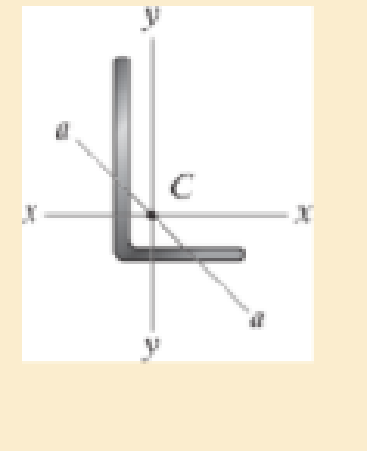
The A992 steel angle has a cross-sectional area of A = 2.48 in2 and a radius of gyration about the x axis of rx = 1.26 in. and about the y axis of ry = 0.879 in. The smallest radius of gyration occurs about the a-a axis and is ra = 0.644 in. If the angle is to be used as a pin-connected 10-ft-long column, determine the largest axial load that can be applied through its centroid C without causing it to buckle.
Want to see the full answer?
Check out a sample textbook solution
Chapter 13 Solutions
Mechanics of Materials Plus Mastering Engineering with Pearson eText - Access Card Package (10th Edition)
Additional Engineering Textbook Solutions
Engineering Mechanics: Statics
Engineering Mechanics: Statics & Dynamics (14th Edition)
Machine Elements in Mechanical Design (6th Edition) (What's New in Trades & Technology)
INTERNATIONAL EDITION---Engineering Mechanics: Statics, 14th edition (SI unit)
Vector Mechanics for Engineers: Statics
Statics and Mechanics of Materials


- Problem 2. The assembly consists of three titanium (Ti- 6A1-4V) rods and a rigid bar AC. The cross-sectional area of each rod is given in the figure. If a force of 6 kip is applied to the ring F, determine the horizontal displacement of point F, and determine the angle of tilt of rigid bar AC. B D 4 ft ACD = 1 in² AAB 6 ft 1.5 in² E 2 ft 1 ft 1 ft AEF = 2 in² 6 kiparrow_forwardThe rigid bar BC is supported by the steel rod AC of cross-sectional area 0.31 in2. Find the vertical displacement (in inches and absolute value) of point Coaused by the 2888-lb load if x = 8.7 ft and 8 = 46.5-. Use E = 29159 ksi for steel. Note: Round off the final answer to four decimal places. Rigid B Parrow_forwardQuestion 1: Given that Tuitow = 50 MPa for the rod AB and tattow = 25 MPa for the rod BC. If T=1250 N.m, find the required radius for both rods. Ahmtmum AB = BC =arrow_forward
- Question 17 A wide flange section has the following properties: bf = 200 mm tf = 8 mm d = 300 mm tw = 11 mm Calculate the radius of gyration in mm about the y-axis.arrow_forward8-26 to 8–31 For each built-up section shown in Figs. P8–26 to P8–31, determine the moment of inertia and the radius of gyration of the section with respect te the horizontal centroidal axis. +12 in. X 1 in. plate 300 mm X 20 mm plate W14 X 61 C250 × 0.438 100 mm 300 mm X 20 mm plate -12 in. X1 in. plate FIGURE P8-26 FIGURE P8-27arrow_forwardThe wires each have a diameter of 1 2 in., length of 2 ft, and are made from 304 stainless steel. If P = 6 kip, determine the angle of tilt of the rigid beam AB.arrow_forward
- 5. Two C310x45 channels are latticed together so they have equal moments of inertia about the principal axes. Determine the minimum length of column having this section, assuming pinned ends, E = 200 GPa, and a proportional limit of 240 MPa. What safe load will the column carry for the length of 12 m with a factor of safety of 2.5? For C310x45, take I = 67.3x10⁻⁶ m4 %3D Ans L = 9.89 m, F = 738 kNarrow_forward3. The aluminum block has the rectangular cross-section and is subjected to an axial compressive force of 8 kips. The 1.5-in side changed its length to 1.50014 inches. Use E = 10 x 10³ ksi. Calculate the new length of the 2-inch side. Answer: Lnew = 2.00019 in 1.5 in 2 in. 8 kip- 8 kip 3 in. 4. A solid cylinder of diameter D is subjected to an axial load P. Show that its change in diameter is 8D = 4Pv/лDE.arrow_forwardThe steel rod has Young’s modulus of 200GPa. Its cross-sectional area is uniform and A=60 ????2, Calculate the displacement of points A and B.arrow_forward
- Determine the moment reaction at point A in the clockwise direction in N.m? Set P =411 N, Y =197 mm, & X= 420 mm. Note: the figure is not to scale and your answer should contain only numbers, not units. 60 30arrow_forwardThe shaft is supported at its ends two bearings A and B and is subjected to the forces applied to the pulleys fixed to the shaft. (Figure 1) The T₁ = 410-N forces act in the -z direction and the 200-N and 80-N forces act in the +y direction. The journal bearings at A and B exert only y and components of force on the shaft. Figure 200 mm 300 mm 150 mm, 150 mm 200 mm 400 mm B 200 N 80 N 80 N 200 N < 1 of 1 Determine the resultant normal force on the cross section at C Express your answer to three significant figures and include appropriate units. Nc= Submit Part B (Vc)y= Submit Part C Value Determine the resultant shear force in the y direction on the cross section at C Express your answer to three significant figures and include appropriate units. (Vc)= = Request Answer 4 ▬▬ μÀ 4 Value Request Answer μà → ⒸIE ? Value Units Determine the resultant shear force in the direction on the cross section at C Express your answer to three significant figures and include appropriate units. Ć IE ?…arrow_forwardThe shaft is supported at its ends by two bearings A and B and is subjected to the forces applied to the pulleys fixed to the shaft. ( Figure 1) The T₁ = 410-N forces act in the -z direction and the 200-N and 80-N forces act in the +y direction. The journal bearings at A and B exert only y and z components of force on the shaft. Figure X 200 mm 300 mm 150 mm 150 mm 200 mm D 400 mm B 200 N 200 N Z 80 N 80 N 1 of 1 > ▾ Part B ▾ Determine the resultant shear force in the y direction on the cross section at C. Express your answer to three significant figures and include appropriate units. (Vc), = 245.71 ▾ Part C Submit Previous Answers Request Answer * Incorrect; Try Again; 4 attempts remaining Submit (Vc), = Value Part D Determine the resultant shear force in the direction on the cross section at C. Express your answer to three significant figures and include appropriate units. T= HA Submit Part E ריהם Determine the resultant torque on the cross section at C Express your answer to three…arrow_forward
 Elements Of ElectromagneticsMechanical EngineeringISBN:9780190698614Author:Sadiku, Matthew N. O.Publisher:Oxford University Press
 Mechanics of Materials (10th Edition)Mechanical EngineeringISBN:9780134319650Author:Russell C. HibbelerPublisher:PEARSON
 Thermodynamics: An Engineering ApproachMechanical EngineeringISBN:9781259822674Author:Yunus A. Cengel Dr., Michael A. BolesPublisher:McGraw-Hill Education
 Control Systems EngineeringMechanical EngineeringISBN:9781118170519Author:Norman S. NisePublisher:WILEY
 Mechanics of Materials (MindTap Course List)Mechanical EngineeringISBN:9781337093347Author:Barry J. Goodno, James M. GerePublisher:Cengage Learning
 Engineering Mechanics: StaticsMechanical EngineeringISBN:9781118807330Author:James L. Meriam, L. G. Kraige, J. N. BoltonPublisher:WILEY