
FUND.OF ELECTRIC CIRCUITS>CUSTOM<
6th Edition
ISBN: 9781307184631
Author: Alexander
Publisher: MCG/CREATE
expand_more
expand_more
format_list_bulleted
Videos
Textbook Question
Chapter 14, Problem 81P
The circuit shown in Fig. 14.98 has the impedance
Find:
- (a) the values of R, L, C, and G
- (b) the element values that will raise the resonant frequency by a factor of 103 by frequency scaling
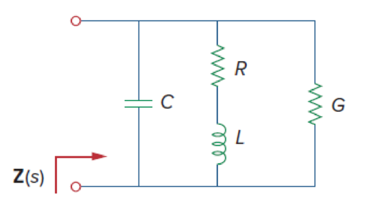
Figure 14.98
Expert Solution & Answer
Want to see the full answer?
Check out a sample textbook solution
Students have asked these similar questions
6.16 Determine the range of K for which the closed-loop systems are stable for each of the cases below by making a Bode plot for K = 1 and imagining the magnitude plot sliding up or down until instability results. Verify your answers by using a very rough sketch of a root-locus plot.
b. KG(s)=K / (s+ 10) (s+ 1)
A 500 µH inductor, 80/π^2 pF capacitor and a 628 ohm resistor are connected to form a series RLC circuit. Calculate the resonant frequency and Q-factor of this circuit at resonance ?
Please answer ASAP
A series RLC circuit in which R = 1.00 Ω, L = 1.00 mH, and C = 1.00 nF is connected to an AC source delivering 1.00 V (rms). (a) Make a precise graph of the power delivered to the circuit as a function of the frequency and (b) verify that the full width of the resonance peak at halfmaximum is R/2πL.
Chapter 14 Solutions
FUND.OF ELECTRIC CIRCUITS>CUSTOM<
Ch. 14.2 - Obtain the transfer function VoVs of the RL...Ch. 14.2 - Prob. 2PPCh. 14.4 - Draw the Bode plots for the transfer function...Ch. 14.4 - Sketch the Bode plots for H()=50j(j+4)(j+10)2Ch. 14.4 - Construct the Bode plots for H(s)=10s(s2+80s+400)Ch. 14.4 - Obtain the transfer function H() corresponding to...Ch. 14.5 - A series-connected circuit has R = 4 and L = 25...Ch. 14.6 - A parallel resonant circuit has R = 100 k, L = 50...Ch. 14.6 - Calculate the resonant frequency of the circuit in...Ch. 14.7 - For the circuit in Fig. 14.40, obtain the transfer...
Ch. 14.7 - Design a band-pass filter of the form in Fig....Ch. 14.8 - Design a high-pass filter with a high-frequency...Ch. 14.8 - Design a notch filter based on Fig. 14.47 for 0 =...Ch. 14.9 - Prob. 14PPCh. 14.10 - Obtain the frequency response of the circuit in...Ch. 14.10 - Consider the network in Fig. 14.57. Use PSpice to...Ch. 14.12 - For an FM radio receiver, the incoming wave is in...Ch. 14.12 - Repeat Example 14.18 for band-pass filter BP6....Ch. 14.12 - If each speaker in Fig. 14.66 has an 8- resistance...Ch. 14 - Prob. 1RQCh. 14 - On the Bode magnitude plot, the slope of 1/5+j2...Ch. 14 - On the Bode phase plot for 0.5 50, the slope of...Ch. 14 - How much inductance is needed to resonate at 5 kHz...Ch. 14 - The difference between the half-power frequencies...Ch. 14 - Prob. 6RQCh. 14 - Prob. 7RQCh. 14 - Prob. 8RQCh. 14 - What kind of filter can be used to select a signal...Ch. 14 - A voltage source supplies a signal of constant...Ch. 14 - Find the transfer function Io/Ii of the RL circuit...Ch. 14 - Using Fig. 14.69, design a problem to help other...Ch. 14 - For the circuit shown in Fig. 14.70, find H(s) =...Ch. 14 - Find the transfer function H(s) = Vo/Vi of the...Ch. 14 - For the circuit shown in Fig. 14.72, find H(s) =...Ch. 14 - For the circuit shown in Fig. 14.73, find H(s) =...Ch. 14 - Calculate |H()| if HdB equals (a) 0.1 dB (b) 5 dB...Ch. 14 - Design a problem to help other students calculate...Ch. 14 - A ladder network has a voltage gain of...Ch. 14 - Design a problem to help other students better...Ch. 14 - Sketch the Bode plots for H()=0.2(10+j)j(2+j)Ch. 14 - A transfer function is given by...Ch. 14 - Construct the Bode plots for...Ch. 14 - Draw the Bode plots for H()=250(j+1)j(2+10j+25)Ch. 14 - Prob. 15PCh. 14 - Sketch Bode magnitude and phase plots for...Ch. 14 - Sketch the Bode plots for G(s)=s(s+2)2(s+1), s = jCh. 14 - A linear network has this transfer function...Ch. 14 - Sketch the asymptotic Bode plots of the magnitude...Ch. 14 - Design a more complex problem than given in Prob....Ch. 14 - Sketch the magnitude Bode plot for...Ch. 14 - Find the transfer function H() with the Bode...Ch. 14 - The Bode magnitude plot of H() is shown in Fig....Ch. 14 - The magnitude plot in Fig. 14.76 represents the...Ch. 14 - A series RLC network has R = 2 k, L = 40 mH, and C...Ch. 14 - Design a problem to help other students better...Ch. 14 - Design a series RLC resonant circuit with 0 = 40...Ch. 14 - Design a series RLC circuit with B = 20 rad/s and...Ch. 14 - Let vs = 20 cos(at) V in the circuit of Fig....Ch. 14 - A circuit consisting of a coil with inductance 10...Ch. 14 - Design a parallel resonant RLC circuit with 0 =...Ch. 14 - Design a problem to help other students better...Ch. 14 - A parallel resonant circuit with a bandwidth of 40...Ch. 14 - A parallel RLC circuit has R = 100 k, L = 100 mH,...Ch. 14 - A parallel RLC circuit has R = 10 k, L = 100 mH,...Ch. 14 - It is expected that a parallel RLC resonant...Ch. 14 - Rework Prob. 14.25 if the elements are connected...Ch. 14 - Find the resonant frequency of the circuit in Fig....Ch. 14 - For the tank circuit in Fig. 14.79, find the...Ch. 14 - Prob. 40PCh. 14 - Using Fig. 14.80, design a problem to help other...Ch. 14 - For the circuits in Fig. 14.81, find the resonant...Ch. 14 - Calculate the resonant frequency of each of the...Ch. 14 - For the circuit in Fig. 14.83, find: (a) the...Ch. 14 - For the circuit shown in Fig. 14.84. find 0, B,...Ch. 14 - For the network illustrated in Fig. 14.85, find...Ch. 14 - Prob. 47PCh. 14 - Find the transfer function Vo/Vs of the circuit in...Ch. 14 - Design a problem to help other students better...Ch. 14 - Determine what type of filter is in Fig. 14.87....Ch. 14 - Design an RL low-pass filter that uses a 40-mH...Ch. 14 - Design a problem to help other students better...Ch. 14 - Design a series RLC type band-pass filter with...Ch. 14 - Design a passive band-stop filter with 0 = 10...Ch. 14 - Determine the range of frequencies that will be...Ch. 14 - (a) Show that for a band-pass filter,...Ch. 14 - Determine the center frequency and bandwidth of...Ch. 14 - The circuit parameters for a series RLC band-stop...Ch. 14 - Find the bandwidth and center frequency of the...Ch. 14 - Obtain the transfer function of a high-pass filter...Ch. 14 - Find the transfer function for each of the active...Ch. 14 - The filter in Fig. 14.90(b) has a 3-dB cutoff...Ch. 14 - Design an active first-order high-pass filter with...Ch. 14 - Obtain the transfer function of the active filter...Ch. 14 - A high-pass filter is shown in Fig. 14.92. Show...Ch. 14 - A general first-order filter is shown in Fig....Ch. 14 - Design an active low-pass filter with dc gain of...Ch. 14 - Design a problem to help other students better...Ch. 14 - Design the filter in Fig. 14.94 to meet the...Ch. 14 - A second-order active filter known as a...Ch. 14 - Use magnitude and frequency scaling on the circuit...Ch. 14 - Design a problem to help other students better...Ch. 14 - Calculate the values of R, L, and C that will...Ch. 14 - Prob. 74PCh. 14 - In an RLC circuit, R = 20 , L = 4 H, and C = 1 F....Ch. 14 - Given a parallel RLC circuit with R = 5 k, L = 10...Ch. 14 - A series RLC circuit has R = 10 , 0 = 40 rad/s,...Ch. 14 - Redesign the circuit in Fig. 14.85 so that all...Ch. 14 - Refer to the network in Fig. 14.96. (a) Find...Ch. 14 - (a) For the circuit in Fig. 14.97, draw the new...Ch. 14 - The circuit shown in Fig. 14.98 has the impedance...Ch. 14 - Scale the low-pass active filter in Fig. 14.99 so...Ch. 14 - The op amp circuit in Fig. 14.100 is to be...Ch. 14 - Using PSpice or MultiSim, obtain the frequency...Ch. 14 - Use PSpice or MultiSim to obtain the magnitude and...Ch. 14 - Using Fig. 14.103, design a problem to help other...Ch. 14 - In the interval 0.1 f 100 Hz, plot the response...Ch. 14 - Use PSpice or MultiSim to generate the magnitude...Ch. 14 - Obtain the magnitude plot of the response Vo in...Ch. 14 - Obtain the frequency response of the circuit in...Ch. 14 - For the tank circuit of Fig. 14.79, obtain the...Ch. 14 - Using PSpice or MultiSim, plot the magnitude of...Ch. 14 - For the phase shifter circuit shown in Fig....Ch. 14 - For an emergency situation, an engineer needs to...Ch. 14 - A series-tuned antenna circuit consists of a...Ch. 14 - The crossover circuit in Fig. 14.108 is a low-pass...Ch. 14 - The crossover circuit in Fig. 14.109 is a...Ch. 14 - A certain electronic test circuit produced a...Ch. 14 - In an electronic device, a series circuit is...Ch. 14 - In a certain application, a simple RC low-pass...Ch. 14 - In an amplifier circuit, a simple RC high-pass...Ch. 14 - Practical RC filter design should allow for source...Ch. 14 - The RC circuit in Fig. 14.111 is used for a lead...Ch. 14 - A low-quality-factor, double-tuned band-pass...
Knowledge Booster


Learn more about
Need a deep-dive on the concept behind this application? Look no further. Learn more about this topic, electrical-engineering and related others by exploring similar questions and additional content below.Similar questions
- Dear Tutor please help me out in this question, your efforts will be appreciated A system is represented by a transfer function as follows: G (s) = 10( s + 3 ) / s(s + 2)(s2 + s + 2) a. Get the frequency response of the above system. b. Sketch Bode diagram of the system above. c. Using the obtained Bode diagram, determine the stabilityarrow_forward1) from rootlocus fig , Determine damping ratio and ( Wn ) of the closed loop system for K=10.2) Sketch the approximate graph of the Bode magnitude of the transfer function (use K=100). Please answer me part 1,2arrow_forwardPlot the bode diagram for the following transfer function and obtain gain margin and phase margin. G(s) = 10/s(1+0.4s)(1+0.1s)arrow_forward
- 388 / 5000 Çeviri sonuçları In the circuit in the figure, Rs = 3.8 kΩ, R1 = 82 kΩ, R2 = 22 kΩ, RC = 5.6 kΩ, RE = 1.5 kΩ and RL = 3.3 kΩ and β = 150.Since the capacitances are C1 = 0.5 μF and C2 = 0.53 μF, what is the low cutoff frequency of the given circuit? NOTE-1: In the middle band frequency, β = 150 will be taken and the frequency dependence of β will not be taken into account. NOTE-2: The output impedance of the transistor r0 will be neglected in the calculations.arrow_forwardG(s)=150(6.25s+1)(s+7)/[s(46.875s+1)(s+5)(s+15)] Draw bode plot using straight linearrow_forwardWhat's the magnitude of frequency response of the closed loop system at w = 2? H(s) = 1/(s+1), G(s) = s-5, K = 4,arrow_forward
- A series RLC circuit is formed using component values R=100 and L=1.5 mH, together with a source that provides a sinusoidal voltage Vs (t). If the quality factor in resonance condition is Q0 = 7, determine: a) the magnitude of the impedance at 500 Mrad s-1b) the current that circulates if vs (t) = 2,5V cos (425 ×10 6t) Note: Vent (input voltage). Vsal (output voltage)arrow_forwardA supply voltage of 3 V is applied to a series R–L–C circuit whose resistance is 12 ohms , inductance is 7.5 mH and capacitance is 0.5µF. Determine (a) the current flowing at resonance, (b) the current flowing at a frequency 2.5% below the resonant frequency and (c) the impedance of the circuit when the frequency is 1% lower than the resonant frequency.arrow_forwardA mass-spring-damper system is shown below and its transfer function is given. Find the spring constant, mass, and damper constant k,m,c of the system according to the Bode diagram given below. Reminder: The starting point of the red line corresponds to -26dB. ζ=0.32. The frequency corresponding to the sloping peak of the red line ω=ωn =3.2arrow_forward
- A hollow pipe (such as an organ pipe open at both ends) is made to go into resonance at frequency f open. One end of the pipe is now covered and the pipe is again made to go into resonance, this time at frequency f closed. Both resonances are first harmonics. How do these two resonances compare? (a) They are the same. (b) f open = 2f closed (c) f closed = 2f open (d) f open = f closed (e) fclosed = 3/2 fopenarrow_forwardCharacteristic equation of a system is given by, s2+3s+31=0 The value of resonant frequency is: Answerarrow_forwardA coil of inductance 200µH and resistance 50.27ohms and a variable capacitor are connected in series to a 5 mV supply of frequency 2MHz. Determine (a) the value of capacitance to tune the circuit to resonance, (b) the supply current at resonance, (c) the p.d. across the capacitor at resonance,the bandwidth, and the half-power frequencies Answers: C= 31.66 pF,I= 99.46 µA,P.D= 250 mV, bandwidth=40 kHz, and half power frequency= 2.02 MHz, 1.98 MHzarrow_forward
arrow_back_ios
SEE MORE QUESTIONS
arrow_forward_ios
Recommended textbooks for you
 Introductory Circuit Analysis (13th Edition)Electrical EngineeringISBN:9780133923605Author:Robert L. BoylestadPublisher:PEARSON
 Delmar's Standard Textbook Of ElectricityElectrical EngineeringISBN:9781337900348Author:Stephen L. HermanPublisher:Cengage Learning
 Programmable Logic ControllersElectrical EngineeringISBN:9780073373843Author:Frank D. PetruzellaPublisher:McGraw-Hill Education
 Fundamentals of Electric CircuitsElectrical EngineeringISBN:9780078028229Author:Charles K Alexander, Matthew SadikuPublisher:McGraw-Hill Education
 Electric Circuits. (11th Edition)Electrical EngineeringISBN:9780134746968Author:James W. Nilsson, Susan RiedelPublisher:PEARSON
 Engineering ElectromagneticsElectrical EngineeringISBN:9780078028151Author:Hayt, William H. (william Hart), Jr, BUCK, John A.Publisher:Mcgraw-hill Education,
Introductory Circuit Analysis (13th Edition)
Electrical Engineering
ISBN:9780133923605
Author:Robert L. Boylestad
Publisher:PEARSON
Delmar's Standard Textbook Of Electricity
Electrical Engineering
ISBN:9781337900348
Author:Stephen L. Herman
Publisher:Cengage Learning
Programmable Logic Controllers
Electrical Engineering
ISBN:9780073373843
Author:Frank D. Petruzella
Publisher:McGraw-Hill Education
Fundamentals of Electric Circuits
Electrical Engineering
ISBN:9780078028229
Author:Charles K Alexander, Matthew Sadiku
Publisher:McGraw-Hill Education
Electric Circuits. (11th Edition)
Electrical Engineering
ISBN:9780134746968
Author:James W. Nilsson, Susan Riedel
Publisher:PEARSON
Engineering Electromagnetics
Electrical Engineering
ISBN:9780078028151
Author:Hayt, William H. (william Hart), Jr, BUCK, John A.
Publisher:Mcgraw-hill Education,
02 - Sinusoidal AC Voltage Sources in Circuits, Part 1; Author: Math and Science;https://www.youtube.com/watch?v=8zMiIHVMfaw;License: Standard Youtube License