FUND.OF ELECTRIC CIRCUITS>CUSTOM<
6th Edition
ISBN: 9781307184631
Author: Alexander
Publisher: MCG/CREATE
bartleby

Concept explainers

bartleby

Videos

Textbook Question
Book Icon
Chapter 14, Problem 79P

Refer to the network in Fig. 14.96.

  1. (a) Find Zin(s).
  2. (b) Scale the elements by Km = 10 and Kf = 100. Find Zin(s) and ω0.
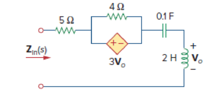
Chapter 14, Problem 79P, Refer to the network in Fig. 14.96. (a) Find Zin(s). (b) Scale the elements by Km = 10 and Kf = 100.

Figure 14.96

(a)

Expert Solution
Check Mark
To determine

Find the value of the input impedance Zin(s) for the network shown in Figure 14.96.

Answer to Problem 79P

The value of the input impedance Zin(s) for the network shown in Figure 14.96 is (5+8s+10s).

Explanation of Solution

Given data:

Refer to Figure 14.96 in the textbook.

Formula used:

Write the expression to calculate the impedance of the passive elements resistor, inductor and capacitor in s-domain.

ZR(s)=R        (1)

ZL(s)=sL        (2)

ZC(s)=1sC        (3)

Here,

R is the value of the resistor,

L is the value of the inductor, and

C is the value of the capacitor.

Calculation:

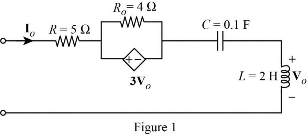
The given circuit is redrawn as Figure 1.

 FUND.OF ELECTRIC CIRCUITS>CUSTOM<, Chapter 14, Problem 79P , additional homework tip  1

Use equation (1) to find ZR(s).

ZR(s)=R

Use equation (1) to find ZRo(s).

ZRo(s)=Ro

Use equation (2) to find ZL(s).

ZL(s)=sL

Use equation (3) to find ZC(s).

ZC(s)=1sC

Insert a 1A voltage source at the terminals and redraw the circuit in Figure 1 using s-domain as Figure 2.

 FUND.OF ELECTRIC CIRCUITS>CUSTOM<, Chapter 14, Problem 79P , additional homework tip  2

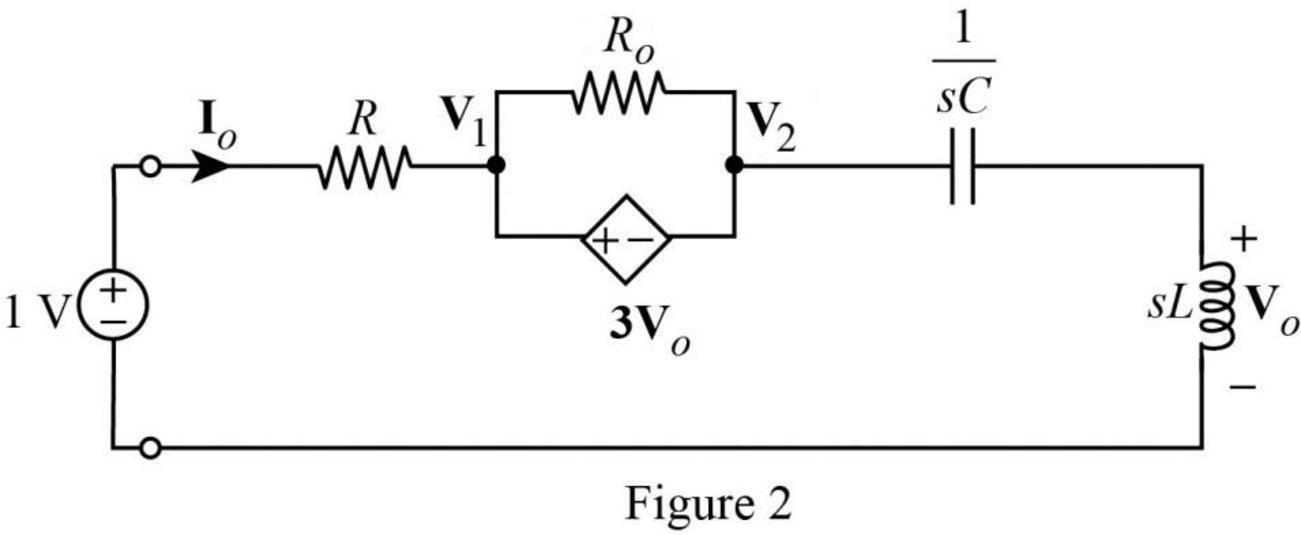
Modify the Figure 2 with the representation of supernode and current direction as shown in Figure 3.

 FUND.OF ELECTRIC CIRCUITS>CUSTOM<, Chapter 14, Problem 79P , additional homework tip  3

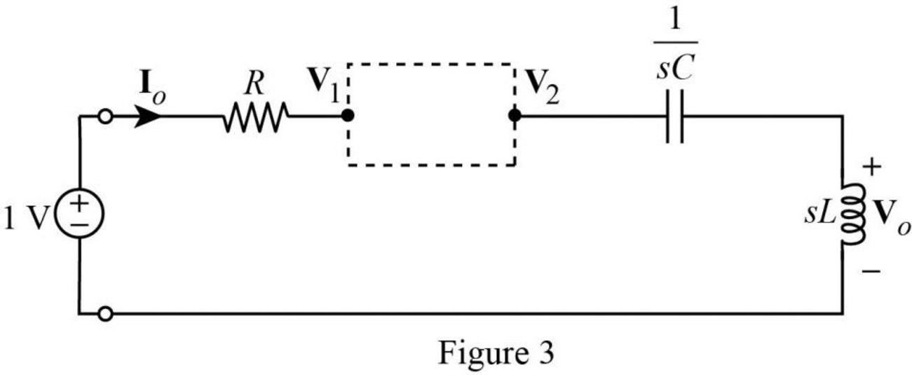
Apply Kirchhoff’s current law to the supernode in Figure 3.

V11R+V2(sL+1sC)=0V11R=V2(sL+1sC)(1V1R)=V2(sL+1sC)

(1V1R)=V2(sL+1sC)        (4)

The Figure 3 is reduced as following Figure 4 to show the voltage relation.

 FUND.OF ELECTRIC CIRCUITS>CUSTOM<, Chapter 14, Problem 79P , additional homework tip  4

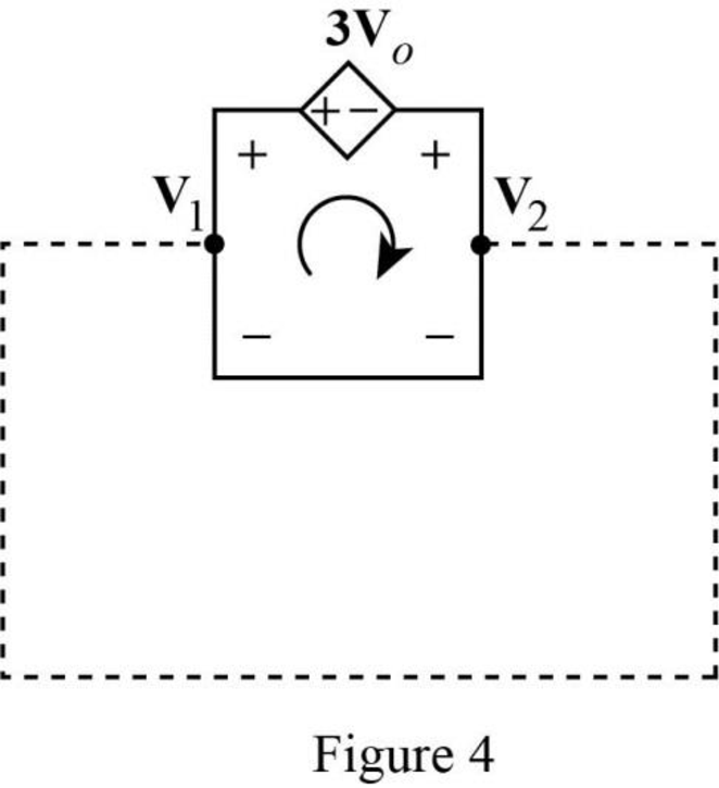
Apply Kirchhoff’s voltage law to the circuit in Figure 4 to obtain the relationship between voltages.

V1+3Vo+V2=03Vo+V2=V1

V2=V13Vo        (5)

Apply voltage division rule on Figure 3 to find Vo.

Vo=sL(sL+1sC)V2

Rearrange the above equation.

VosL=V2(sL+1sC)        (6)

Rearrange the equation (6) to find V2.

V2=(sL+1sC)sLVo=(s2LC+1sC)sLVo=(1+s2LCs2LC)Vo

Substitute (1+s2LCs2LC)Vo for V2 in equation (5).

(1+s2LCs2LC)Vo=V13VoVo+s2LCVo=s2LCV13s2LCVoVo+s2LCVo+3s2LCVo=s2LCV1Vo(1+4s2LC)=s2LCV1

Rearrange the above equation to find Vo.

Vo=s2LC1+4s2LCV1

Compare the equations (4) and (6) to obtain the following equation.

1V1R=VosL1V1=RVosL

Substitute s2LC1+4s2LCV1 for Vo in above equation.

1V1=R(s2LC1+4s2LCV1)sL=s2RLCsL(1+4s2LC)V1=sRC(1+4s2LC)V1

Rearrange the above equation.

V1+sRC(1+4s2LC)V1=1V1(1+sRC(1+4s2LC))=1V1(1+4s2LC+sRC1+4s2LC)=1V1(1+4s2LC+sRC)=1+4s2LC

Simplify the above equation to find V1.

V1=1+4s2LC1+4s2LC+sRC

Refer to Figure 3, the current Io is calculated as follows.

Io=1V1R

Substitute 1+4s2LC1+4s2LC+sRC for V1 in above equation to find Io.

Io=(1(1+4s2LC1+4s2LC+sRC)R)=((1+4s2LC+sRC14s2LC1+4s2LC+sRC)R)=sRCR(1+4s2LC+sRC)=sC(1+4s2LC+sRC)

The input impedance of the circuit in Figure 2 is calculated as follows.

Zin(s)=1VIo

Substitute sC(1+4s2LC+sRC) for Io in above equation to find Zin(s).

Zin(s)=1(sC(1+4s2LC+sRC))=1+4s2LC+sRCsC=1sC+4s2LCsC+sRCsC

Zin(s)=R+4sL+1sC        (7)

Substitute 5Ω for R, 2H for L and 0.1F for C in equation (7) to find Zin(s).

Zin(s)=5+4s(2)+1s(0.1)=(5+8s+10s)

Substitute jω for s in equation (7) to find Zin(ω).

Zin(ω)=R+4(jω)L+1(jω)C=R+j4ωL+1jωC=R+j4ωLjωC=R+j(4ωL1ωC)

At resonance condition, the imaginary part of the impedance should be equal to zero. Therefore, equate the imaginary part of the above equation to zero.

4ω0L1ω0C=04ω02LC1ω0C=04ω02LC1=04ω02LC=1

Simplify the above equation to find ω02.

ω02=14LC

Take square root on both sides of the above equation to find ω0.

ω02=14LCω0=14LC

ω0=12LC        (8)

Substitute 2H for L and 0.1F for C in equation (8) to find ω0.

ω0=12(2H)(0.1F)=120.2(s2FF) {1H=1s21F}=1.118rads

Conclusion:

Thus, the value of the input impedance Zin(s) for the network shown in Figure 14.96 is (5+8s+10s).

(b)

Expert Solution
Check Mark
To determine

Find the value of the input impedance Zin(s) and resonant frequency after scaling the elements by Km=10 and Kf=100.

Answer to Problem 79P

The value of the input impedance Zin(s) and resonant frequency (ω0) after scaling of the elements is 50+0.8s+104s and 111.8rads respectively.

Explanation of Solution

Given data:

The value of the magnitude scaling factor (Km) is 10.

The value of the frequency scaling factor (Kf) is 100.

Formula used:

Consider the equations used in magnitude and frequency scaling.

Write the expression to calculate the scaled resistor.

R=KmR        (9)

Here,

Km is the magnitude scaling factor.

Write the expression to calculate the scaled inductor.

L=KmKfL        (10)

Here,

Kf is the frequency scaling factor.

Write the expression to calculate the scaled capacitor.

C=1KmKfC        (11)

Calculation:

Substitute 5Ω for R and 10 for Km in equation (9) to find R.

R=(10)(5Ω)=50Ω

Substitute 2H for L, 10 for Km and 100 for Kf in equation (10) to find L.

L=10100(2H)=0.2H

Substitute 0.1F for C, 10 for Km and 100 for Kf in equation (11) to find C.

C=0.1F(10)(100)=1×10⁴F

Substitute 50Ω for R, 0.2H for L and 1×10⁴F for C in equation (7) to find Zin(s).

Zin(s)=(50)+4s(0.2)+1s(104)=(50+0.8s+104s)

Substitute 0.2H for L and 1×10⁴F for C in equation (8) to find ω0.

ω0=12(0.2H)(1×10⁴F)=12(2×10⁵)(s2FF) {1H=1s21F}=111.8rads

Conclusion:

Thus, the value of the input impedance Zin(s) and resonant frequency (ω0) after scaling of the elements is 50+0.8s+104s and 111.8rads respectively.

Want to see more full solutions like this?

Subscribe now to access step-by-step solutions to millions of textbook problems written by subject matter experts!
Students have asked these similar questions
A 500 µH inductor, 80/π^2 pF capacitor and a 628 ohm resistor are connected to form a series RLC circuit. Calculate the resonant frequency and Q-factor of this circuit at resonance ? Please answer ASAP
What's the magnitude of frequency response of the closed loop system at w = 2? H(s) = 1/(s+1), G(s) = s-5, K = 4,
Calculate all the values from the formulas given below: Area = 402.88mm^2, Capacitance = 1.11592 x 10^-10 F length = 12.03 mm, fr (resonance frequency) = 108828.238, fa (anti resonance frequency) = 145987.807, Diameter of cylinder = 4mm, Mass of cylinder = 4.38g,

Chapter 14 Solutions

FUND.OF ELECTRIC CIRCUITS>CUSTOM<

Ch. 14.7 - Design a band-pass filter of the form in Fig....Ch. 14.8 - Design a high-pass filter with a high-frequency...Ch. 14.8 - Design a notch filter based on Fig. 14.47 for 0 =...Ch. 14.9 - Prob. 14PPCh. 14.10 - Obtain the frequency response of the circuit in...Ch. 14.10 - Consider the network in Fig. 14.57. Use PSpice to...Ch. 14.12 - For an FM radio receiver, the incoming wave is in...Ch. 14.12 - Repeat Example 14.18 for band-pass filter BP6....Ch. 14.12 - If each speaker in Fig. 14.66 has an 8- resistance...Ch. 14 - Prob. 1RQCh. 14 - On the Bode magnitude plot, the slope of 1/5+j2...Ch. 14 - On the Bode phase plot for 0.5 50, the slope of...Ch. 14 - How much inductance is needed to resonate at 5 kHz...Ch. 14 - The difference between the half-power frequencies...Ch. 14 - Prob. 6RQCh. 14 - Prob. 7RQCh. 14 - Prob. 8RQCh. 14 - What kind of filter can be used to select a signal...Ch. 14 - A voltage source supplies a signal of constant...Ch. 14 - Find the transfer function Io/Ii of the RL circuit...Ch. 14 - Using Fig. 14.69, design a problem to help other...Ch. 14 - For the circuit shown in Fig. 14.70, find H(s) =...Ch. 14 - Find the transfer function H(s) = Vo/Vi of the...Ch. 14 - For the circuit shown in Fig. 14.72, find H(s) =...Ch. 14 - For the circuit shown in Fig. 14.73, find H(s) =...Ch. 14 - Calculate |H()| if HdB equals (a) 0.1 dB (b) 5 dB...Ch. 14 - Design a problem to help other students calculate...Ch. 14 - A ladder network has a voltage gain of...Ch. 14 - Design a problem to help other students better...Ch. 14 - Sketch the Bode plots for H()=0.2(10+j)j(2+j)Ch. 14 - A transfer function is given by...Ch. 14 - Construct the Bode plots for...Ch. 14 - Draw the Bode plots for H()=250(j+1)j(2+10j+25)Ch. 14 - Prob. 15PCh. 14 - Sketch Bode magnitude and phase plots for...Ch. 14 - Sketch the Bode plots for G(s)=s(s+2)2(s+1), s = jCh. 14 - A linear network has this transfer function...Ch. 14 - Sketch the asymptotic Bode plots of the magnitude...Ch. 14 - Design a more complex problem than given in Prob....Ch. 14 - Sketch the magnitude Bode plot for...Ch. 14 - Find the transfer function H() with the Bode...Ch. 14 - The Bode magnitude plot of H() is shown in Fig....Ch. 14 - The magnitude plot in Fig. 14.76 represents the...Ch. 14 - A series RLC network has R = 2 k, L = 40 mH, and C...Ch. 14 - Design a problem to help other students better...Ch. 14 - Design a series RLC resonant circuit with 0 = 40...Ch. 14 - Design a series RLC circuit with B = 20 rad/s and...Ch. 14 - Let vs = 20 cos(at) V in the circuit of Fig....Ch. 14 - A circuit consisting of a coil with inductance 10...Ch. 14 - Design a parallel resonant RLC circuit with 0 =...Ch. 14 - Design a problem to help other students better...Ch. 14 - A parallel resonant circuit with a bandwidth of 40...Ch. 14 - A parallel RLC circuit has R = 100 k, L = 100 mH,...Ch. 14 - A parallel RLC circuit has R = 10 k, L = 100 mH,...Ch. 14 - It is expected that a parallel RLC resonant...Ch. 14 - Rework Prob. 14.25 if the elements are connected...Ch. 14 - Find the resonant frequency of the circuit in Fig....Ch. 14 - For the tank circuit in Fig. 14.79, find the...Ch. 14 - Prob. 40PCh. 14 - Using Fig. 14.80, design a problem to help other...Ch. 14 - For the circuits in Fig. 14.81, find the resonant...Ch. 14 - Calculate the resonant frequency of each of the...Ch. 14 - For the circuit in Fig. 14.83, find: (a) the...Ch. 14 - For the circuit shown in Fig. 14.84. find 0, B,...Ch. 14 - For the network illustrated in Fig. 14.85, find...Ch. 14 - Prob. 47PCh. 14 - Find the transfer function Vo/Vs of the circuit in...Ch. 14 - Design a problem to help other students better...Ch. 14 - Determine what type of filter is in Fig. 14.87....Ch. 14 - Design an RL low-pass filter that uses a 40-mH...Ch. 14 - Design a problem to help other students better...Ch. 14 - Design a series RLC type band-pass filter with...Ch. 14 - Design a passive band-stop filter with 0 = 10...Ch. 14 - Determine the range of frequencies that will be...Ch. 14 - (a) Show that for a band-pass filter,...Ch. 14 - Determine the center frequency and bandwidth of...Ch. 14 - The circuit parameters for a series RLC band-stop...Ch. 14 - Find the bandwidth and center frequency of the...Ch. 14 - Obtain the transfer function of a high-pass filter...Ch. 14 - Find the transfer function for each of the active...Ch. 14 - The filter in Fig. 14.90(b) has a 3-dB cutoff...Ch. 14 - Design an active first-order high-pass filter with...Ch. 14 - Obtain the transfer function of the active filter...Ch. 14 - A high-pass filter is shown in Fig. 14.92. Show...Ch. 14 - A general first-order filter is shown in Fig....Ch. 14 - Design an active low-pass filter with dc gain of...Ch. 14 - Design a problem to help other students better...Ch. 14 - Design the filter in Fig. 14.94 to meet the...Ch. 14 - A second-order active filter known as a...Ch. 14 - Use magnitude and frequency scaling on the circuit...Ch. 14 - Design a problem to help other students better...Ch. 14 - Calculate the values of R, L, and C that will...Ch. 14 - Prob. 74PCh. 14 - In an RLC circuit, R = 20 , L = 4 H, and C = 1 F....Ch. 14 - Given a parallel RLC circuit with R = 5 k, L = 10...Ch. 14 - A series RLC circuit has R = 10 , 0 = 40 rad/s,...Ch. 14 - Redesign the circuit in Fig. 14.85 so that all...Ch. 14 - Refer to the network in Fig. 14.96. (a) Find...Ch. 14 - (a) For the circuit in Fig. 14.97, draw the new...Ch. 14 - The circuit shown in Fig. 14.98 has the impedance...Ch. 14 - Scale the low-pass active filter in Fig. 14.99 so...Ch. 14 - The op amp circuit in Fig. 14.100 is to be...Ch. 14 - Using PSpice or MultiSim, obtain the frequency...Ch. 14 - Use PSpice or MultiSim to obtain the magnitude and...Ch. 14 - Using Fig. 14.103, design a problem to help other...Ch. 14 - In the interval 0.1 f 100 Hz, plot the response...Ch. 14 - Use PSpice or MultiSim to generate the magnitude...Ch. 14 - Obtain the magnitude plot of the response Vo in...Ch. 14 - Obtain the frequency response of the circuit in...Ch. 14 - For the tank circuit of Fig. 14.79, obtain the...Ch. 14 - Using PSpice or MultiSim, plot the magnitude of...Ch. 14 - For the phase shifter circuit shown in Fig....Ch. 14 - For an emergency situation, an engineer needs to...Ch. 14 - A series-tuned antenna circuit consists of a...Ch. 14 - The crossover circuit in Fig. 14.108 is a low-pass...Ch. 14 - The crossover circuit in Fig. 14.109 is a...Ch. 14 - A certain electronic test circuit produced a...Ch. 14 - In an electronic device, a series circuit is...Ch. 14 - In a certain application, a simple RC low-pass...Ch. 14 - In an amplifier circuit, a simple RC high-pass...Ch. 14 - Practical RC filter design should allow for source...Ch. 14 - The RC circuit in Fig. 14.111 is used for a lead...Ch. 14 - A low-quality-factor, double-tuned band-pass...
Knowledge Booster
Background pattern image
Electrical Engineering
Learn more about
Need a deep-dive on the concept behind this application? Look no further. Learn more about this topic, electrical-engineering and related others by exploring similar questions and additional content below.
Similar questions
SEE MORE QUESTIONS
Recommended textbooks for you
Text book image
Introductory Circuit Analysis (13th Edition)
Electrical Engineering
ISBN:9780133923605
Author:Robert L. Boylestad
Publisher:PEARSON
Text book image
Delmar's Standard Textbook Of Electricity
Electrical Engineering
ISBN:9781337900348
Author:Stephen L. Herman
Publisher:Cengage Learning
Text book image
Programmable Logic Controllers
Electrical Engineering
ISBN:9780073373843
Author:Frank D. Petruzella
Publisher:McGraw-Hill Education
Text book image
Fundamentals of Electric Circuits
Electrical Engineering
ISBN:9780078028229
Author:Charles K Alexander, Matthew Sadiku
Publisher:McGraw-Hill Education
Text book image
Electric Circuits. (11th Edition)
Electrical Engineering
ISBN:9780134746968
Author:James W. Nilsson, Susan Riedel
Publisher:PEARSON
Text book image
Engineering Electromagnetics
Electrical Engineering
ISBN:9780078028151
Author:Hayt, William H. (william Hart), Jr, BUCK, John A.
Publisher:Mcgraw-hill Education,
Current Divider Rule; Author: Neso Academy;https://www.youtube.com/watch?v=hRU1mKWUehY;License: Standard YouTube License, CC-BY