
Videos
Determine the bending strain energy in the simply supported beam. Solve the problem two ways, (a) Apply Eq. 14–17. (b) The load w dx acting on the segment dx of the beam is displaced a distance y, where y = w(−x4 + 2Lx3 − L3x)/(24EI), the equation of the elastic curve. Hence the internal strain energy in the differential segment dx of the beam is equal to the external work, i.e.,
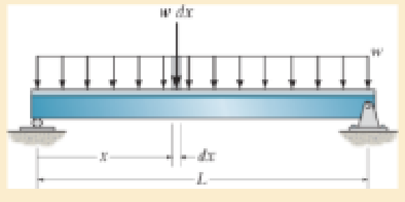
Prob. 14–24
Want to see the full answer?
Check out a sample textbook solution
Chapter 14 Solutions
Mechanics of Materials
Additional Engineering Textbook Solutions
Engineering Mechanics: Dynamics (14th Edition)
INTERNATIONAL EDITION---Engineering Mechanics: Statics, 14th edition (SI unit)
Shigley's Mechanical Engineering Design (McGraw-Hill Series in Mechanical Engineering)
Fundamentals of Heat and Mass Transfer
Statics and Mechanics of Materials (5th Edition)
Applied Fluid Mechanics (7th Edition)


- A shaft is made of a polymer having an elliptical cross section. If it resists an internal moment of M = 50 N # m, determine the maximum bending stress in the material (a) using the flexure formula, where Iz = 1 4 p(0.08 m)(0.04 m)3, (b) using integration. Sketch a three-dimensional view of the stress distribution acting over the cross-sectional area. Here Ix = 1 4 p(0.08 m)(0.04 m)3.arrow_forwardM = 2. A beam of length 10 m and of uniform rectangular section is supported at its ends and carries uniformly distributed load over the entire length. Calculate the depth of the section if the maximum permissible bending stress is 16 N/mm² and central deflection is not to exceed 10 mm. Take the value of E = 1.2 × 10⁴ N/mm². Use the following g equations: w.L² 8 ус W.L 161 8 d = 2 W.L 8 == WL³ 5 384 ΕΙ (: W = w.L)arrow_forwardDetermine the rotation (slope) and displacement at point B of the frame. Bending stiffness (EI) is constantarrow_forward
- A beam is made from polypropylene plastic and has a stress–strain diagram that can be approximated by the curve shown. If the beam is subjected to a maximum tensile and compressive strain of P = 0.02 mm>mm, determine the moment M.arrow_forward3.0 m 7.95 KN B -9 kN T 2.0 m 1.95 KN 1. Draw the load diagram. 2. Draw the moment diagram. 6.0 m 2º curve D -10.05 KN 2.0 m 16 KN E 2.0 m 3. Determine reaction supports at point A and B. 4. Determine the location of the point of zero shear between supports from support B. Load Diagram 20 KN V Diagram The shear diagram of beam ABCDEF with overhang at both ends is shown in the figure.arrow_forwardDetermine the ff: •Internal bending moment at point c •internal shear force at point c •internal normal force at point c Asap please.arrow_forward
- Determine the absolute maximum normal stress (in unit of MPa) in the beam with external loadings shown below. The beam has a uniform square cross-section with lateral size a = 0.2 m. Note: (1) the shear and moment diagrams can be calculated by either section method or graphical method; (2) there is a concentrated load at point A and a bending moment at point C. 20 kN w = 20 kN/m Mc = = 80 kN · m || В A¬Q C y 2 m 2 m 2 marrow_forwardF1 F2 M B E Determine the shear force and bending moment in the beam. Use F1 = 1100 N, F2 = 900 N, M=900 N.m, and a = 1.5 m. The shear force in the section AC in N is (round to the nearest integer): N The shear force in the section CD in N is (round to the nearest integer): N The shear force in the secetion DE in N is (round to the nearest integer): N The shear force in the section EB in N is (round to the nearest integer): N The bending moment at the point C in N.m is (round to the nearest integer): N.m The bending moment at the point E in N.m is (round to the nearest integer): N.marrow_forwardA leaf spring 75 cm long is required to carry a central load of 8 kN. If the central deflection is not to exceed 2 cm and bending stress no greater than 200 MPa, determine the thickness, width and number of plates. Also compute the radius to which plates should be curved. As- sume width of plate to be 12 times its thickness and E = 200 GPa.arrow_forward
- Select the section modulus of a beam with a rectangular cross section. B E bh² 6 bh³ 3 12 hb2 4 6²h2 2 bh³ 3arrow_forwardDetermine the equations of the elastic curve for the shaft using the X1 and x, coordinates. Take El as constant and Mo = 600 N.m. M, А B X1 - X2 4 m 1 m Select one: V1 (x) = (1/EI). (25 x1 - 400 x1) (m) and V2 (X) = (1/EI). (300 x2? + 1400 x 1100) {m}arrow_forwardThe beam safely supports shear forces and bending moments of 2kN and 6.5 kN-m respectively. Based on this criterion, can it be safely subjected to the loads F = 1kN and C = 1.6 kN-m? Use the area methodarrow_forward
 Elements Of ElectromagneticsMechanical EngineeringISBN:9780190698614Author:Sadiku, Matthew N. O.Publisher:Oxford University Press
 Mechanics of Materials (10th Edition)Mechanical EngineeringISBN:9780134319650Author:Russell C. HibbelerPublisher:PEARSON
 Thermodynamics: An Engineering ApproachMechanical EngineeringISBN:9781259822674Author:Yunus A. Cengel Dr., Michael A. BolesPublisher:McGraw-Hill Education
 Control Systems EngineeringMechanical EngineeringISBN:9781118170519Author:Norman S. NisePublisher:WILEY
 Mechanics of Materials (MindTap Course List)Mechanical EngineeringISBN:9781337093347Author:Barry J. Goodno, James M. GerePublisher:Cengage Learning
 Engineering Mechanics: StaticsMechanical EngineeringISBN:9781118807330Author:James L. Meriam, L. G. Kraige, J. N. BoltonPublisher:WILEY