
Loose Leaf for Engineering Circuit Analysis Format: Loose-leaf
9th Edition
ISBN: 9781259989452
Author: Hayt
Publisher: Mcgraw Hill Publishers
expand_more
expand_more
format_list_bulleted
Videos
Textbook Question
Chapter 15, Problem 2E
For the RL circuit in Fig. 15.52, switch the positions of the resistor and inductor such that vout is the voltage drop across the resistor. (a) Write an expression or the transfer function, defined as H(jω) = vout/vin; (b) for the case of R = 200 Ω and L = 5 mH, construct a plot of the magnitude and phase as a function of frequency; and (c) evaluate the magnitude and phase at a frequency of 10 kHz.
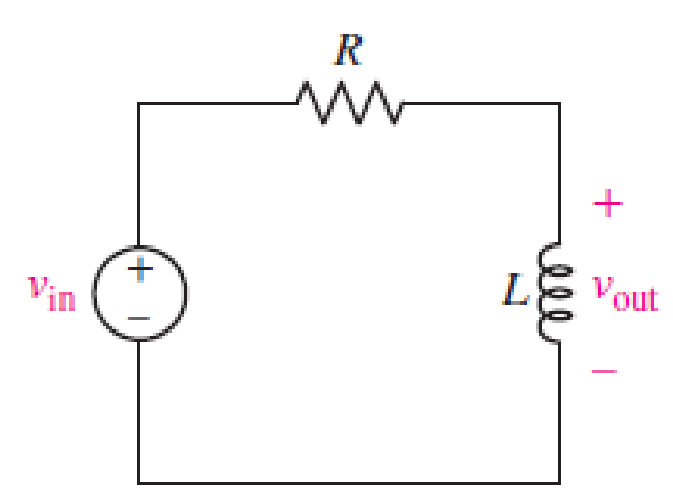
■ FIGURE 15.52
Expert Solution & Answer
Want to see the full answer?
Check out a sample textbook solution
Students have asked these similar questions
1. A series RLC circuit has a Q of 75 and a pass band between half-power frequencies of 160 cps. Calculate the frequency of resonance and upper and lower frequencies of the pass band.
2. A 15.9 uF capacitor and a 15.1 mH inductor are connected in parallel. In series with these units are a variable resistor R and an adjustable device X, joined in series. (a) Determine the kind and size of device X (inductance in Henry or capacitance in Farad) when the circuit is connected to a 50 volt 400 cps source and is adjusted to resonance. (b) For the resonant condition, calculate the value of R if the voltage drop across the paralleled units is to be 100 volts.
3. An impedance coil having a resistance of 30 ohms and a 50 cps inductive reactance of 33.3 ohms is connected to a 125 volt 60 cps source. A series circuit consisting of a 20 ohm resistor and a variable capacitor is then connected in parallel with the coil. (a) for what values of capacitance will the circuit be in resonance? (b)…
What will be the oscillator frequency of the Hartley oscillator if inductance L1, L2 are equal to 1mH and 2mH, respectively, and capacitor C is 10nF? (Neglect mutual inductance)
R= 300 ohm, L= 40 mH, C= 600nF, V(AC)=5 Volt, F= 100 Hz
Calculate theoretically the voltages XL (Inductance = Resistance of the coil), XC (Capacitance = resistance of the capacitor), Z (Impedance = Equivalent resistance of the circuit), VL, VC, VLC and the current value I (mA). Also explain the relationship of XL and XC with frequency in two words. Write the relation that gives the resonant frequency.
Chapter 15 Solutions
Loose Leaf for Engineering Circuit Analysis Format: Loose-leaf
Ch. 15.1 - Write an expression for the transfer function of...Ch. 15.2 - Calculate HdB at = 146 rad/s if H(s) equals (a)...Ch. 15.2 - Prob. 3PCh. 15.2 - Draw the Bode phase plot for the transfer function...Ch. 15.2 - Construct a Bode magnitude plot for H(s) equal to...Ch. 15.2 - Draw the Bode phase plot for H(s) equal to (a)...Ch. 15.2 - Prob. 7PCh. 15.3 - A parallel resonant circuit is composed of the...Ch. 15.3 - Prob. 9PCh. 15.4 - A marginally high-Q parallel resonant circuit has...
Ch. 15.5 - A series resonant circuit has a bandwidth of 100...Ch. 15.6 - Referring to the circuit of Fig. 15.25a, let R1 =...Ch. 15.6 - Prob. 13PCh. 15.6 - Prob. 14PCh. 15.6 - The series combination of 10 and 10 nF is in...Ch. 15.7 - A parallel resonant circuit is defined by C = 0.01...Ch. 15.8 - Design a high-pass filter with a cutoff frequency...Ch. 15.8 - Design a bandpass filter with a low-frequency...Ch. 15.8 - Design a low-pass filter circuit with a gain of 30...Ch. 15 - For the RL circuit in Fig. 15.52, (a) determine...Ch. 15 - For the RL circuit in Fig. 15.52, switch the...Ch. 15 - Examine the series RLC circuit in Fig. 15.53, with...Ch. 15 - For the circuit in Fig. 15.54, (a) derive an...Ch. 15 - For the circuit in Fig. 15.55, (a) derive an...Ch. 15 - For the circuit in Fig. 15.56, (a) determine the...Ch. 15 - For the circuit in Fig. 15.57, (a) determine the...Ch. 15 - Sketch the Bode magnitude and phase plots for the...Ch. 15 - Use the Bode approach to sketch the magnitude of...Ch. 15 - If a particular network is described by transfer...Ch. 15 - Use MATLAB to plot the magnitude and phase Bode...Ch. 15 - Determine the Bode magnitude plot for the...Ch. 15 - Determine the Bode magnitude and phase plot for...Ch. 15 - Prob. 15ECh. 15 - Prob. 16ECh. 15 - For the circuit of Fig. 15.56, construct a...Ch. 15 - Construct a magnitude and phase Bode plot for the...Ch. 15 - For the circuit in Fig. 15.54, use LTspice to...Ch. 15 - For the circuit in Fig. 15.55, use LTspice to...Ch. 15 - Prob. 21ECh. 15 - A certain parallel RLC circuit is built using...Ch. 15 - A parallel RLC network is constructed using R = 5...Ch. 15 - Prob. 24ECh. 15 - Delete the 2 resistor in the network of Fig....Ch. 15 - Delete the 1 resistor in the network of Fig....Ch. 15 - Prob. 28ECh. 15 - Prob. 29ECh. 15 - Prob. 30ECh. 15 - A parallel RLC network is constructed with a 200 H...Ch. 15 - Prob. 32ECh. 15 - A parallel RLC circuit is constructed such that it...Ch. 15 - Prob. 34ECh. 15 - Prob. 35ECh. 15 - An RLC circuit is constructed using R = 5 , L = 20...Ch. 15 - Prob. 37ECh. 15 - Prob. 38ECh. 15 - For the network of Fig. 15.25a, R1 = 100 , R2 =...Ch. 15 - Assuming an operating frequency of 200 rad/s, find...Ch. 15 - Prob. 41ECh. 15 - Prob. 42ECh. 15 - For the circuit shown in Fig. 15.64, the voltage...Ch. 15 - Prob. 44ECh. 15 - Prob. 45ECh. 15 - Prob. 46ECh. 15 - The filter shown in Fig. 15.66a has the response...Ch. 15 - Prob. 48ECh. 15 - Examine the filter for the circuit in Fig. 15.68....Ch. 15 - Examine the filter for the circuit in Fig. 15.69....Ch. 15 - (a)Design a high-pass filter with a corner...Ch. 15 - (a) Design a low-pass filter with a break...Ch. 15 - Prob. 53ECh. 15 - Prob. 54ECh. 15 - Design a low-pass filter characterized by a...Ch. 15 - Prob. 56ECh. 15 - The circuit in Fig. 15.70 is known as a notch...Ch. 15 - (a) Design a two-stage op amp filter circuit with...Ch. 15 - Design a circuit which removes the entire audio...Ch. 15 - Prob. 61ECh. 15 - If a high-pass filter is required having gain of 6...Ch. 15 - (a) Design a second-order high-pass Butterworth...Ch. 15 - Design a fourth-order high-pass Butterworth filter...Ch. 15 - (a) Design a Sallen-Key low-pass filter with a...Ch. 15 - (a) Design a Sallen-Key low-pass filter with a...Ch. 15 - A piezoelectric sensor has an equivalent circuit...Ch. 15 - Design a parallel resonant circuit for an AM radio...Ch. 15 - The network of Fig. 15.72 was implemented as a...Ch. 15 - Determine the effect of component tolerance on the...
Additional Engineering Textbook Solutions
Find more solutions based on key concepts
How many coulombs do 93.8 1016 electrons represent?
Principles Of Electric Circuits
Design an ideal inverting op-amp circuit such that the voltage gain is Av=25 . The maximum current in any resis...
Microelectronics: Circuit Analysis and Design
When travelers from the USA and Canada visit Europe, they encounter a different power distribution system. Wall...
Electric machinery fundamentals
Identify the type of input and output configuration for each diff-amp in Figure 18-35.
Electronics Fundamentals: Circuits, Devices & Applications
The current source in the circuit shown generates the current pulse
Find (a) v (0); (b) the instant of time gr...
Electric Circuits. (11th Edition)
Write the nodal equations for the network of Fig. 8.137 using the general approach. Find the nodal voltages usi...
Introductory Circuit Analysis (13th Edition)
Knowledge Booster


Learn more about
Need a deep-dive on the concept behind this application? Look no further. Learn more about this topic, electrical-engineering and related others by exploring similar questions and additional content below.Similar questions
- A series L–R–C circuit has a supply input of 5 volts. Given that inductance, L = 5 mH, resistance, R = 75ohm and capacitance, C = 0.2µF, determine (a) the resonant frequency, (b) the value of voltage across the capacitor at the resonant frequency, (c) the frequency at which the p.d. across the capacitance is a maximum and (d) the value of the maximum voltage across the capacitor. A capacitor having a Q-factor of 250 is con nected in series with a coil which has a Q-factor of 80. Calculate the overall Q-factor of the circuit.arrow_forwardA series R L C circuit is operating in a resonance mode. The input voltage signal is: u (t ) =150square root of 2 sin (1000 t - 45deg), V . Find the capacitance C, the characteristic impedance ρ, the quality factor Q, the effective (RMS) values of the voltage drops across the passive elements. Given are: R = 10 Ω, L=100 mH. Use the condition for voltage resonance.arrow_forwardRC=10 kΩ, RE=5 kΩ, RL=2.2 kΩ, CS=10 µF, CC=1 µF, CE=20 µF, Cbe=20 pF, Cbc=10 pF,VT=26mV, β=100, ro=sonsuz vcc=20 RS=1 kΩ, R1=40 kΩ, R2=10 Find the gain of the circuit below and the lower and upper cutoff frequencies.arrow_forward
- When the Nyquist diagram of the given system is drawn, which is the frequency value at which the graph cuts the virtual axis? A 0 rad/sec B 2 rad/sec C 1.732 rad/sec D -2 rad/sec E 1.41 rad/secarrow_forwardA series RLC circuit is formed using component values R=100 and L=1.5 mH, together with a source that provides a sinusoidal voltage Vs (t). If the quality factor in resonance condition is Q0 = 7, determine: a) the magnitude of the impedance at 500 Mrad s-1b) the current that circulates if vs (t) = 2,5V cos (425 ×10 6t) Note: Vent (input voltage). Vsal (output voltage)arrow_forwardCalculate all the values from the formulas given below: Area = 402.88mm^2, Capacitance = 1.11592 x 10^-10 F length = 12.03 mm, fr (resonance frequency) = 108828.238, fa (anti resonance frequency) = 145987.807, Diameter of cylinder = 4mm, Mass of cylinder = 4.38g,arrow_forward
- Determine and sketch the magnitude response and system response of the following LCCDE system : .arrow_forwardA summary of the results is as follows: Frequency = 1.01 kHz: Input = 1.51 V; Output = 1.44 V Frequency = 10.06 kHz: Input = 1.37 V; Output = 0.62 V Frequency = 102.8 kHz: Input = 1.31 V; Output = 90 mV The resistor was measured to be 331.4 Ω and the capacitor to be 96.3 nF. (1) Calculate values of the transfer function, using the formula above, at the frequencies that were investigated and compare them to the ratios of the measured output and input voltages at each frequency. A summary of the results is as follows: Frequency = 1.01 kHz: Input = 1.50 V; Output = 1.44 V Frequency = 10.06 kHz: Input = 1.20 V; Output = 0.50 V Frequency = 102.8 kHz: Input = 1.13 V; Output = 70 mV The resistor was measured to be 150.1 Ω and the capacitor to be 233.6 nF. (2) Are the ratios of the output voltage to input voltage for this filter similar to the ratios of the first low-pass filter? Does it make sense based on the transfer function how the ratios compare?arrow_forward1. The mathematical expression of the frequency spectrum of a general FM signal shows that it has technically a limited bandwidth a wide bandwidth an infinite bandwidth narrow bandwidth none of the choices 2. The break frequency for commercial FM broadcast of the preemphasis and deemphasis network is 2.122 kHz 2122 kHz 75 kHz 75 Hz none of the choicesarrow_forward
- A causal LTI system is described by the following equation: y[n] – ay[n-1] = b x[n] + x[n-1] where a is real and less than 1 in magnitude. a) Find a value of b such that magnitude of the frequency response of the system is one for all Ω. b) Find and plot the output of this system with a = 1/2 when the input is x[n] = (1/2)n u[n]arrow_forward1. An impedance coil takes 144 watts at a lagging power factor of 0.6. What value of capacitanceand resistance should be connected in series with the coil if the power input to the latter is toremain unchanged and the overall power factor is to be unity (in resonance)? The circuit isenergized by a 120 volt, 60 cps source.2. A series RLC circuit has a Q of 75 and a pass band between half-power frequencies of 160 cps.Calculate the frequency of resonance and upper and lower frequencies of the pass band.3. An impedance coil having a resistance of 30 ohms and a 50 cps inductive reactance of 33.3 ohmsis connected to a 125 volt 60 cps source. A series circuit consisting of a 20 ohm resistor and avariable capacitor is then connected in parallel with the coil. (a) for what values of capacitancewill the circuit be in resonance? (b) calculate the two values of line current for the condition ofresonance.4. A parallel-series filter like that of Fig. 13.10b in the scanned copy of the on page 364 is…arrow_forwardA superheterodyne receiver is to tune the range 88.1MHz to 107.1MHz. The RF circuit inductance is 1μH. Low-side injection is used.a. Calculate the minimum capacitance of the variable capacitor in the RF circuitb. Calculate the RF circuit capacitance tuning ratio c. If the receiver has a single converter stage and IF of 800kHz, calculate the capacitance tuning ratio of the local oscillator d. If the maximum capacitance of the variable capacitor of the local oscillator is 0.2pF, calculate the minimum capacitance e. If the receiver has a single converter stage and IF of 800kHz, calculate the image frequency of 103.7MHzf. Calculate the IFRR (in dB) of (e) if Q of the preselector is 50 g. To increase the IFRR of (e) to 40dB, double conversion is used. What must be the frequency of the 1st IF?arrow_forward
arrow_back_ios
SEE MORE QUESTIONS
arrow_forward_ios
Recommended textbooks for you
 Introductory Circuit Analysis (13th Edition)Electrical EngineeringISBN:9780133923605Author:Robert L. BoylestadPublisher:PEARSON
 Delmar's Standard Textbook Of ElectricityElectrical EngineeringISBN:9781337900348Author:Stephen L. HermanPublisher:Cengage Learning
 Programmable Logic ControllersElectrical EngineeringISBN:9780073373843Author:Frank D. PetruzellaPublisher:McGraw-Hill Education
 Fundamentals of Electric CircuitsElectrical EngineeringISBN:9780078028229Author:Charles K Alexander, Matthew SadikuPublisher:McGraw-Hill Education
 Electric Circuits. (11th Edition)Electrical EngineeringISBN:9780134746968Author:James W. Nilsson, Susan RiedelPublisher:PEARSON
 Engineering ElectromagneticsElectrical EngineeringISBN:9780078028151Author:Hayt, William H. (william Hart), Jr, BUCK, John A.Publisher:Mcgraw-hill Education,
Introductory Circuit Analysis (13th Edition)
Electrical Engineering
ISBN:9780133923605
Author:Robert L. Boylestad
Publisher:PEARSON
Delmar's Standard Textbook Of Electricity
Electrical Engineering
ISBN:9781337900348
Author:Stephen L. Herman
Publisher:Cengage Learning
Programmable Logic Controllers
Electrical Engineering
ISBN:9780073373843
Author:Frank D. Petruzella
Publisher:McGraw-Hill Education
Fundamentals of Electric Circuits
Electrical Engineering
ISBN:9780078028229
Author:Charles K Alexander, Matthew Sadiku
Publisher:McGraw-Hill Education
Electric Circuits. (11th Edition)
Electrical Engineering
ISBN:9780134746968
Author:James W. Nilsson, Susan Riedel
Publisher:PEARSON
Engineering Electromagnetics
Electrical Engineering
ISBN:9780078028151
Author:Hayt, William H. (william Hart), Jr, BUCK, John A.
Publisher:Mcgraw-hill Education,
Resonance Circuits: LC Inductor-Capacitor Resonating Circuits; Author: Physics Videos by Eugene Khutoryansky;https://www.youtube.com/watch?v=Mq-PF1vo9QA;License: Standard YouTube License, CC-BY